
Electron beam welding machine

A technology of electron beam and welding machine, which is applied in the direction of electron beam welding equipment, welding equipment, metal processing equipment, etc., can solve the problems of insufficient utilization of vacuum chambers, and achieve the effect of improving the processing range of workpieces, reasonable structure, and easy disassembly and assembly

Pending Publication Date: 2020-06-09
XIAMEN UNIV OF TECH
View PDF0 Cites 0 Cited by
  • Summary
  • Abstract
  • Description
  • Claims
  • Application Information

AI Technical Summary

Problems solved by technology

The electron gun of this type of electron beam welding equipment is fixed, and the welding process is completed by the movement of the workpiece. The electron gun is generally installed in the center of one surface of the vacuum chamber, so the workpiece can be processed larger than the general volume of the vacuum chamber. Insufficient utilization of the vacuum chamber

Method used


Image

  • Electron beam welding machine
  • Electron beam welding machine
  • Electron beam welding machine

Examples


Embodiment

[0039] Below in conjunction with accompanying drawing and specific embodiment the present invention is described in further detail:

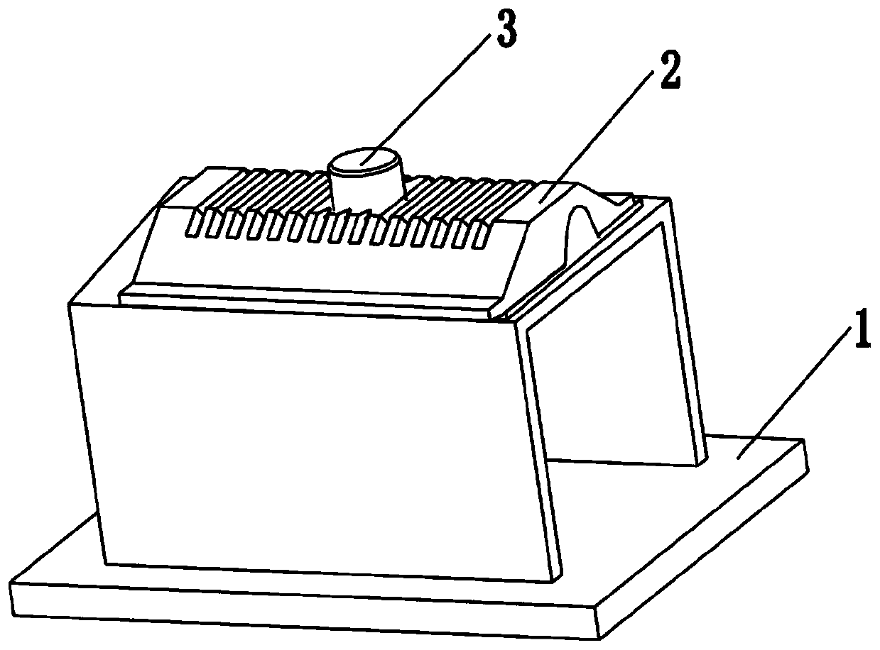
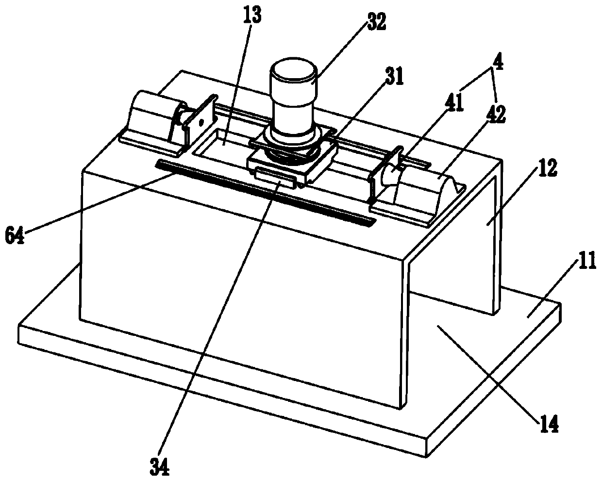
[0040] Depend on figure 1 As shown, the present invention provides an electron beam welding machine, which includes a frame mechanism 1 , a sealing mechanism 2 , a welding torch mechanism 3 and a driving mechanism 4 .

[0041]The frame mechanism 1 includes a frame built with a welding cavity 14 for vacuuming, and the frame is provided with a first opening 13 communicating with the welding cavity 14 . Such as figure 2 As shown, the base includes a base base 11 and a base body 12 arranged on the top of the base base 11. The base body 12 has a welding cavity 14 for vacuuming inside the base body 12. The top surface of the base body 12 A first opening 13 communicating with the welding cavity 14 is opened.

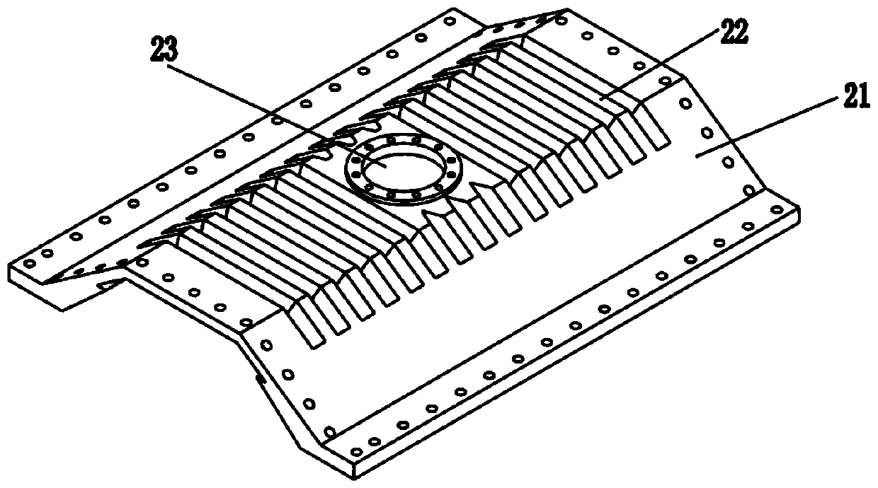
[0042] The sealing mechanism 2 includes a sealant seat 21 arranged on the machine base mechanism 1 and covering and sealing the first openin...


PUM


Abstract

The invention provides an electron beam welding machine, and relates to the technical field of welding. The electron beam welding machine comprises a machine seat mechanism, a sealing mechanism, a welding gun mechanism and a drive mechanism. The machine seat mechanism is provided with a first opening communicating with a welding cavity. The sealing mechanism comprises a sealant seat arranged on the machine seat mechanism and used for covering and sealing the first opening, and the sealant seat is provided with a wrinkle segment capable of stretching and contacting left and right. The welding gun mechanism comprises a gun seat arranged on the machine seat mechanism in a manner of being capable of moving left and right and an electronic gun arranged on the gun seat, the tail end of the electronic gun penetrates out of the sealant seat in a sealed manner, and the front end of the electronic gun penetrates through the first opening and stretches into the welding cavity. The drive mechanismcomprises drive parts arranged on the machine seat mechanism and used for driving the gun seat to move left and right. The drive parts can drive the gun seat and drive the electronic gun to move leftand right relative to a machine seat, and the wrinkle segment is stretched and compressed. The structure of the electron beam welding machine is simple, motion of the electronic gun outside a vacuumchamber can be achieved, the utilization rate to the vacuum chamber is high, and the machining range of workpieces can be increased to a certain degree.

Description

technical field [0001] The invention relates to the field of welding, in particular to an electron beam welding machine. Background technique [0002] At present, the existing electron beam welding equipment can be divided into two categories from the placement of the electron gun: [0003] One is that the electron gun is inside the vacuum chamber, and the movement of the electron gun is controlled by a rail motor or a manipulator to complete welding. The electron guns of electron beam welding equipment with this type of structure are generally movable, but since all mechanical parts are installed inside the vacuum chamber, they occupy the inner space of the vacuum chamber to a large extent, which will increase the cost of vacuuming. [0004] The other type is that the electron gun passes through one face of the vacuum chamber and is fixed and sealed. The electron gun of this type of electron beam welding equipment is fixed, and the welding process is completed by the move...

Claims


Application Information

Patent Timeline
IPC IPC(8): B23K15/06B23K15/00
CPCB23K15/0026B23K15/0046B23K15/06
Inventor 李胜波白凤民刘许勋
Owner XIAMEN UNIV OF TECH
Learn More