Inclined two-stage micro-oil gasification burner

An oil burner, oblique insertion technology, applied in the direction of burner, combustion method, combustion type, etc., can solve the problems of low combustion efficiency, black smoke, high price, etc., reduce product specifications and varieties, and improve the perimeter Simple and reliable effect of temperature and structure

Active Publication Date: 2016-08-24
YANTAI LONGYUAN POWER TECH
View PDF6 Cites 0 Cited by
  • Summary
  • Abstract
  • Description
  • Claims
  • Application Information

AI Technical Summary

Problems solved by technology

like figure 1 As shown, the existing conventional large oil gun burner includes an oil gun a1, an ignition gun a2, a travel switch assembly a3, a combined pneumatic actuator a4, an air distributor a5, a burner a6 and a solenoid valve box (not shown in the figure). shown), it can be seen from the figure that the travel switch assembly a3, the combined pneumatic actuator a4, the burner a6 and the electromagnetic valve box have very complicated structures, and the combustion efficiency is not high, which will occur when the cold furnace is ignited. Black smoke, it is difficult to meet the country's energy-saving and environmental protection requirements, and for explosion-proof occasions, solenoid valves, travel switches, etc. need to be explosion-proof, which is expensive and greatly increases the manufacturing cost of large oil gun burners

Method used


Image

  • Inclined two-stage micro-oil gasification burner
  • Inclined two-stage micro-oil gasification burner
  • Inclined two-stage micro-oil gasification burner

Examples


Embodiment Construction

[0019] The technical solutions of the present invention will be described in further detail below with reference to the accompanying drawings and embodiments.

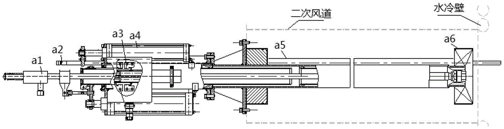
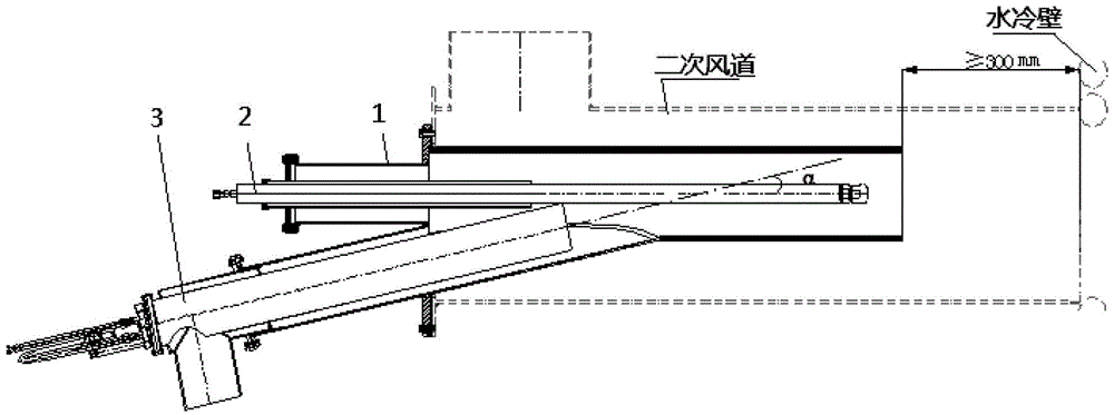
[0020] Such as figure 2 As shown, it is a schematic structural diagram of an embodiment of the obliquely inserted two-stage micro-oil gasification burner of the present invention. In this embodiment, the inclined two-stage micro-oil gasification burner includes an air distribution tube 1 , a primary oil burner 3 and a secondary oil gun 2 . The air distribution cylinder 1 is installed in the secondary air duct, and the secondary oil gun 2 is horizontally arranged in the air distribution cylinder 1, and the primary oil burner 3 is obliquely inserted into the air distribution cylinder 1. Wherein, the axis of the direction in which the primary oil burner 3 is inserted into the air distribution cylinder 1 and the axis of the direction in which the secondary oil gun 2 is inserted into the air distribution cylinder 1 form a...


PUM


Abstract

The invention relates to an oblique insertion type two-stage micro oil gasification burner which comprises an air distribution barrel, a first-stage oil burner body and a second-stage oil gun. The air distribution barrel is mounted in a secondary air duct. The second-stage oil gun is horizontally arranged in the air distribution barrel. The first-stage oil burner body is inserted into the air distribution barrel obliquely. The axis of the insertion direction of the first-stage oil burner body into the air distribution barrel and the axis of the insertion direction of the second-stage oil gun into the air distribution barrel form an acute angle. The flame of the first-stage oil burner body is used for lighting and stabilizing the flame of the second-stage oil gun and heating and gasifying the fuel oil of the second-stage oil gun. Compared with an existing large oil gun burner, multiple expensive components are omitted, the structure is simpler and more reliable, and manufacturing cost is lower. The first-stage oil burner body heats and gasifies the fuel oil of the second-stage oil gun, and original cold oil atomization burning of the second-stage oil gun is converted into hot oil gas burning of the second-stage oil gun. The boundary temperature during burning of the second-stage oil gun can be raised through high-temperature smoke generated during burning of the first-stage oil burner body, and therefore the oblique insertion type two-stage micro oil gasification burner has extremely high burning efficiency.

Description

technical field [0001] The invention relates to an oil burner for a boiler, in particular to an obliquely inserted two-stage micro-oil gasification burner. Background technique [0002] In the power industry, thermal power plants often use large oil gun burners when the boiler is started or stabilized. Such as figure 1 As shown, the existing conventional large oil gun burner includes an oil gun a1, an ignition gun a2, a travel switch assembly a3, a combined pneumatic actuator a4, an air distributor a5, a burner a6 and a solenoid valve box (not shown in the figure). shown), it can be seen from the figure that the travel switch assembly a3, the combined pneumatic actuator a4, the burner a6 and the electromagnetic valve box have very complicated structures, and the combustion efficiency is not high, which will occur when the cold furnace is ignited. Black smoke is emitted, which is difficult to meet the country's energy-saving and environmental protection requirements, and fo...

Claims


Application Information

Patent Timeline
Patent Type & Authority Patents(China)
IPC IPC(8): F23D11/44F23D11/36
CPCF23D11/36F23D11/446F23D2204/10F23D2206/00
Inventor 蔡巍曹琴付玉玲孙继国李本伟姜志军王鹏姜进东
Owner YANTAI LONGYUAN POWER TECH
Why Eureka
Try Eureka