Unlock instant, AI-driven research and patent intelligence for your innovation.

Capacitive rotary position encoder and capacitive rotary position detection method

A technology of rotating position and encoder, which is applied in the direction of using electric device, converting sensor output, and using electric/magnetic device to transmit sensing member, etc., to achieve the effect of determining the rotating position

Active Publication Date: 2017-04-12
LEICA GEOSYSTEMS AG
View PDF13 Cites 0 Cited by
  • Summary
  • Abstract
  • Description
  • Claims
  • Application Information

AI Technical Summary

Problems solved by technology

Components for evaluating larger numbers of channels (e.g., 50 or more channels) are not used as standard, or require additional hardware expense due to multiplexer circuits, etc.

Method used


Image

  • Capacitive rotary position encoder and capacitive rotary position detection method
  • Capacitive rotary position encoder and capacitive rotary position detection method
  • Capacitive rotary position encoder and capacitive rotary position detection method

Examples


Embodiment Construction

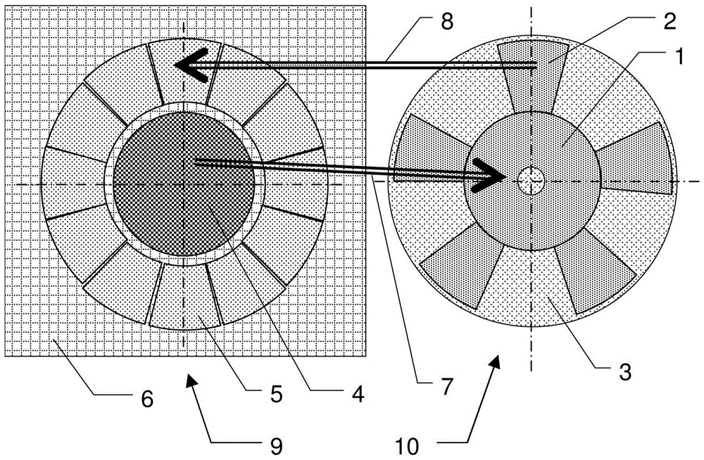
[0061] figure 1 One embodiment of a capacitive rotary position encoder according to the invention for the absolute determination of the rotational position about a rotational axis is shown. This rotary position encoder has a transceiver unit 9 comprising a first arrangement of N conductive capacitive sensitive areas 5, which are implemented as angular nodes with a predetermined angular range and are uniformly distributed over the periphery part. In this case, the predetermined angular range is in particular approximately 360° / N, so that it can be deduced that the spacing between the sensitive areas 5 is substantially negligibly small, in particular smaller than said angular range several orders of magnitude.

[0062] Furthermore, the transceiver unit 9 has an electrically conductive reference area 4 and an evaluation circuit by means of which the capacitance value between the reference area 4 and one of the sensitive areas 5 can be determined.

[0063] In this case, the sen...


PUM


Abstract

The invention relates to a capacitive rotary position encoder and a capacitive rotary position detection method. The encoder comprises a transceiver unit and a counterpart, the transceiver unit comprising: a first arrangement of N conductive capacitive sensitive areas, the sensitive areas being implemented as angular segments uniformly distributed on the periphery and having a predetermined angular range; conductive reference Area and evaluation circuit, the capacitance value between the reference area and one of the sensitive areas can be determined by the evaluation circuit. The sensitive area and the reference area are implemented as conductor track structures on the first electronic printed circuit board. The counterpart is opposite to the transceiver unit and can rotate relative to the transceiver unit around the rotation axis, and includes: a reference coupling area, which is arranged opposite to the reference area; an arrangement formed by X≥3 conductive code areas, which Electrically connected to the reference coupling region. The code area is embodied as an angular segment having at least approximately the same predetermined angular range as the sensitive area and is arranged in a rotationally asymmetric angular distribution with respect to the axis of rotation.

Description

technical field [0001] The invention relates to a capacitive rotary position encoder and a method for capacitive rotary position determination. Background technique [0002] The invention relates in particular to the technical field of capacitive rotary position encoders, in which the overlapping of conductive areas separated with respect to one another by a dielectric and in this case varying said conductive areas varies with rotational position Rotational position is determined with the aid of capacitance values ​​between. According to a simplified theoretical model, in this case the resulting capacitance value is proportional to the area overlap ratio. [0003] In this case, in a rotary encoder, the conductive areas can be rotated contactlessly one above the other using an air gap as a dielectric, with the result that no mechanical wear of the sensor system occurs. In addition to gases such as air, rotary encoders of this type can also be operated with liquids as dielec...

Claims


Application Information

Patent Timeline
Patent Type & Authority Patents(China)
IPC IPC(8): G01D5/24G01D5/241G01B7/30
CPCG01D5/2415
Inventor 彼得·弗勒S·维尔特切
Owner LEICA GEOSYSTEMS AG
Features
  • R&D
  • Intellectual Property
  • Life Sciences
  • Materials
  • Tech Scout
  • Unparalleled Data Quality
  • Higher Quality Content
  • 60% Fewer Hallucinations
Learn More