optical module

An optical module and optical fiber technology, applied in the field of optical communication, can solve the problems of optical lens module deviating from the coupling position, deteriorating optical path coupling effect, lack of high strength, etc., to achieve improved consistency and accuracy, improved performance, and high fixed strength Effect

Active Publication Date: 2019-01-22
HISENSE BROADBAND MULTIMEDIA TECH
View PDF4 Cites 0 Cited by
  • Summary
  • Abstract
  • Description
  • Claims
  • Application Information

AI Technical Summary

Problems solved by technology

UV glue is a kind of glue that can be cured quickly when exposed to ultraviolet light, but its strength is low, and then black glue needs to be cured at high temperature
During the manual operation before the black glue is cured, due to the lack of high-strength mechanical fixation among the lasers, optical lens modules and optical fibers that make up the optical path, it is very easy to cause the optical lens module to deviate from the coupling position, resulting in poor coupling effect of the optical path

Method used


Image

  • optical module
  • optical module
  • optical module

Examples


Embodiment Construction

[0028] The technical solutions of the present invention will be further described in detail below in conjunction with the accompanying drawings and specific embodiments.

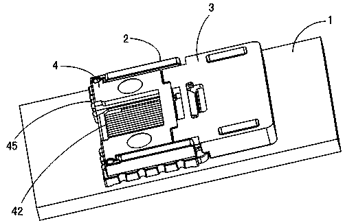
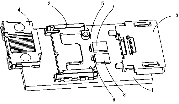
[0029] Please refer to figure 1 and figure 2 An embodiment of the optical module of the present invention is shown, wherein, figure 1 is a schematic diagram of the optical path coupling structure of this embodiment, figure 2 yes figure 1 Schematic diagram of the explosion structure.

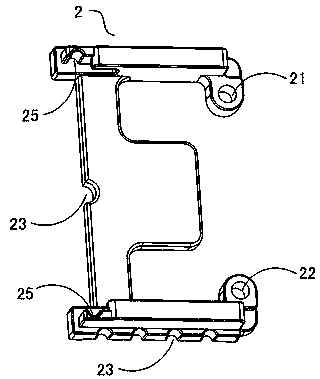
[0030] Such as figure 1 and figure 2 indicated, combined with image 3 As shown in the schematic diagram of the front structure of the fixed bracket, the optical module of this embodiment includes a PCB board 1, a fixed bracket 2 is fixed on the PCB board 1, and two left and right positioning holes 21 and 22 are arranged on the fixed bracket 2, and the positioning Between the holes 21 and 22, a laser array 5 as a light-emitting element of the optical module and a photodetector array 6 as a light-receiving element are ...


PUM


Abstract

The invention discloses an optical module. The optical module includes a PCB board, an optical element arranged on the PCB board, an optical fiber coupled with the optical element through an optical lens module, and a fixed bracket, which is detachable from the fixed bracket. A connected lens holder and an optical fiber holder detachably connected to the lens holder, the fixed holder is fixed on the PCB board, the optical lens module is arranged on the lens holder, and the optical fiber is arranged on the optical fiber holder The optical element is located between the fixed bracket and the lens bracket, the fixed bracket is provided with at least two positioning components, and the lens bracket is provided with positioning components that match the fixed bracket. To achieve the corresponding positioning parts of the detachable connection. Moreover, the coupling of optical paths is realized through mechanical fixation between multiple brackets, which simplifies the process, reduces the coupling cost, and improves the coupling consistency and accuracy.

Description

[0001] This patent application is a divisional application with the application number 2013101186130, the application date is April 8, 2013, and the invention title is "Optical Module and Its Optical Path Coupling Method". technical field [0002] The present invention relates to optical communication technology, in particular to an optical module. Background technique [0003] In existing optical communication technologies, optical signals are used as information carriers for high-speed, long-term, and reliable information transmission. As a core component in the field of optical communication, the coupling effect between the optical element and the transmission path (optical fiber) in the optical module greatly affects the optical signal strength and signal quality, and becomes one of the key factors affecting information transmission. [0004] At present, there are two methods of optical coupling between optical components and transmission fibers in optical modules: activ...

Claims


Application Information

Patent Timeline
Patent Type & Authority Patents(China)
IPC IPC(8): G02B6/32G02B6/42
CPCG02B6/32G02B6/4204
Inventor 黄永亮刘一诚
Owner HISENSE BROADBAND MULTIMEDIA TECH
Why Eureka
Try Eureka