Eureka AIR delivers breakthrough ideas for toughest innovation challenges, trusted by R&D personnel around the world.

Image display method and device

A technology of image display and pixel position, applied in image communication, digital output to display equipment, TV, etc., can solve the problems of wasting transmission resources and processing resources, occupying large bandwidth resources, etc.

Active Publication Date: 2015-01-14
ZHEJIANG DAHUA TECH CO LTD
View PDF3 Cites 10 Cited by
  • Summary
  • Abstract
  • Description
  • Claims
  • Application Information

AI Technical Summary

Problems solved by technology

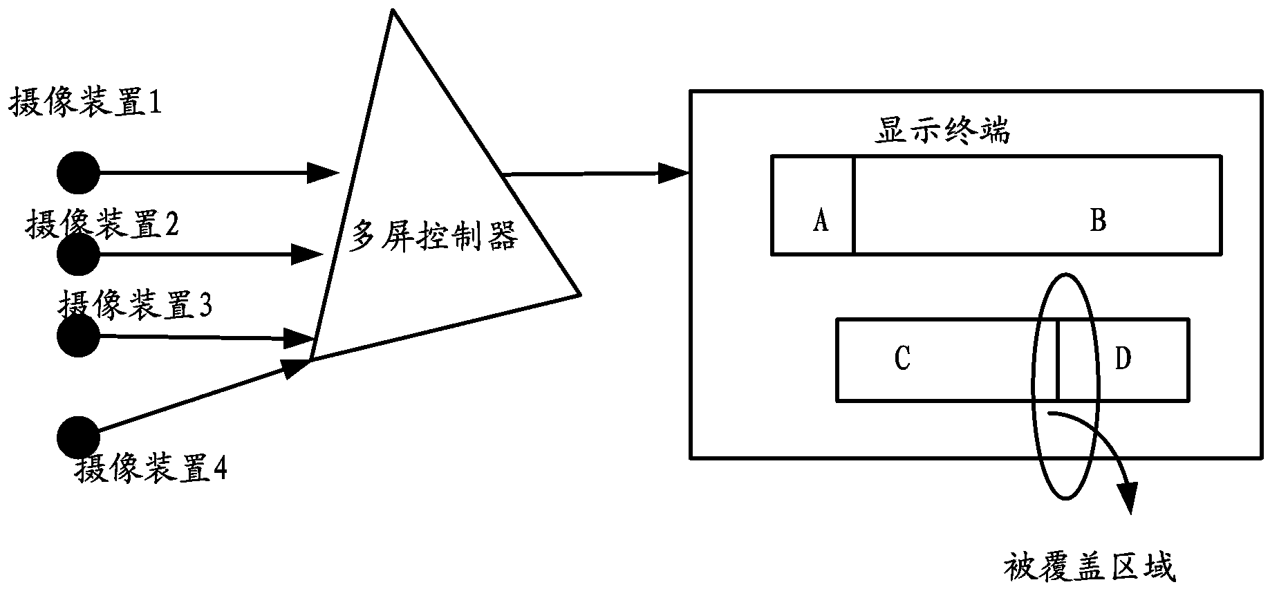
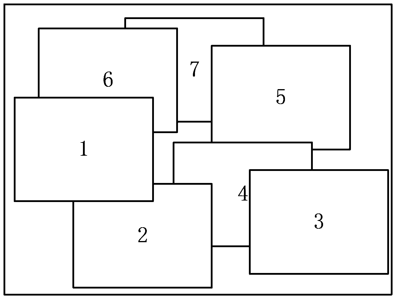
In this image display method, when the multi-screen controller realizes the multi-screen display, the display area needs to be divided. Since the division of the display area is limited by the row and column collection of the video source transmitted by the camera device, its The realization principle is based on quadrilateral coordinates. The final segmented display area is a horizontal and vertical rectangular area. These rectangular areas can be superimposed or covered, but when these display areas are used for video presentation, the covered display The image of the area is still presented, that is, the video data of the invisible part will also be displayed in the background. If multiple display areas display video at the same time, it needs to occupy a large bandwidth resource to transmit the video data.
[0004] To sum up, in the image display method proposed in the prior art, the video data of the invisible part in the display area will also be received and displayed in the background, which wastes transmission resources and processing resources

Method used


Image

  • Image display method and device
  • Image display method and device
  • Image display method and device

Examples


Embodiment Construction

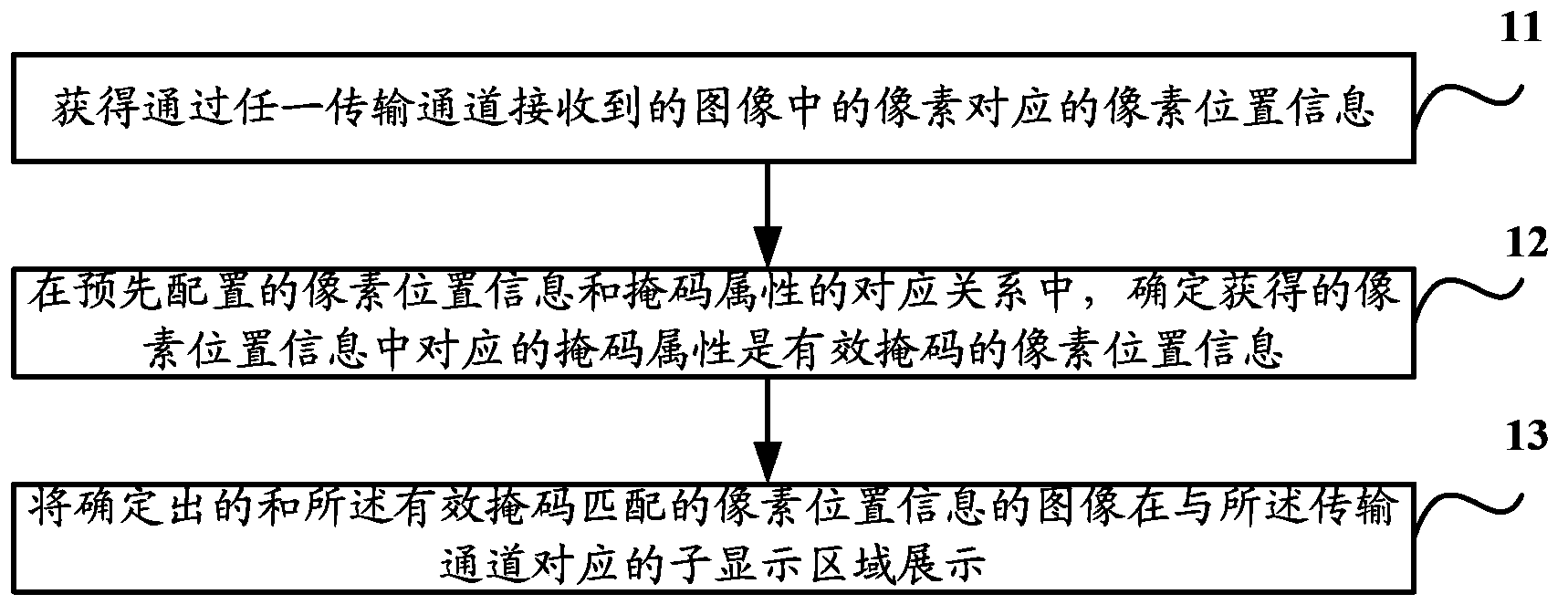
[0015] Aiming at the problem that the video data of the invisible part in the display area proposed in the prior art will also be received and displayed in the background, which wastes transmission resources and processing resources, in the technical solution proposed here in the embodiment of the present invention, by introducing pixel The corresponding relationship between the position information and the mask attribute, determine the pixel position information sent by any transmission channel that matches the effective mask attribute contained in the mask attribute, and finally compare the image with the determined pixel position information with the image in the transmission channel The display of the corresponding display area can better solve the invisible part of the display area, and the video data will not be transmitted, which can better save transmission resources and processing resources.

[0016] The main realization principles, specific implementation methods and ...


PUM


Abstract

The invention discloses an image display method and device, so that display areas can be well partitioned into any shape and overlapped in any layer for displaying video images, and universality is good. The method includes the steps that pixel position information corresponding to pixels in an image received by any transmission channel is obtained; according to the corresponding relation of pre-configured pixel position information and mask attributes, the mask attribute corresponding to the obtained pixel position information is determined as pixel position information of an effective mask, wherein the mask attributes contain effective masks corresponding to pixel position information of visual parts of display subareas obtained after all display areas of a user terminal are partitioned and ineffective masks corresponding to pixel position information of non-visual parts of display subareas obtained after all the display areas of the user terminal are partitioned; determined images of the pixel position information matched with the effective masks are displayed in the display subareas corresponding to the transmission channels.

Description

technical field [0001] The present invention relates to the technical field of image display, in particular to an image display method and device. Background technique [0002] In the field of video surveillance, such as figure 1 As shown, the image display system includes at least one camera, a multi-screen controller, and a display terminal. The display terminal can be a personal computer or an integrated module. The multi-screen controller may be, but not limited to, an independent control device, or an integrated module integrated in a display terminal or a camera device. The camera device transmits the captured video data to the multi-screen controller, and the multi-screen controller controls the display terminal to present the received video data to the user. The display terminal can also be a projection device, which presents the video data received by the multi-screen controller on the TV wall or the screen. [0003] Wherein, when the multi-screen controller cont...

Claims


Application Information

Patent Timeline
Patent Type & Authority Applications(China)
IPC IPC(8): G06F3/14H04N7/18
CPCG06F3/14H04N7/181
Inventor 盛剑国张兴明傅利泉朱江明吴军吴坚
Owner ZHEJIANG DAHUA TECH CO LTD
Why Eureka
Eureka Blog
Learn More