A state monitoring terminal structure for electrical protection pressure plate

A technology for electrical protection and monitoring terminals, which is applied in the direction of electrical components, circuit devices, information technology support systems, etc., can solve the problems of poor working stability, inconvenient installation, use and operation of status monitoring terminals, and achieve optimal installation structure design and setting operations Convenience and improved work stability

Inactive Publication Date: 2016-08-24
DAZHOU POWER BUREAU SICHUAN ELECTRIC POWER +1
View PDF4 Cites 0 Cited by
  • Summary
  • Abstract
  • Description
  • Claims
  • Application Information

AI Technical Summary

Problems solved by technology

[0009] In view of the above-mentioned deficiencies in the prior art, the purpose of the present invention is to provide a condition monitoring terminal structure for the electrical protection pressure plate, which solves the poor working stability of the condition monitoring terminal in the prior art through structural improvement, installation, The problem of inconvenient operation

Method used


Image

  • A state monitoring terminal structure for electrical protection pressure plate
  • A state monitoring terminal structure for electrical protection pressure plate
  • A state monitoring terminal structure for electrical protection pressure plate

Examples


Embodiment Construction

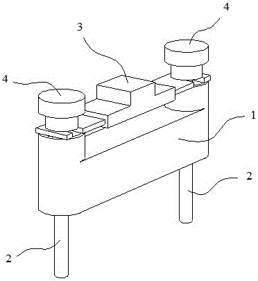
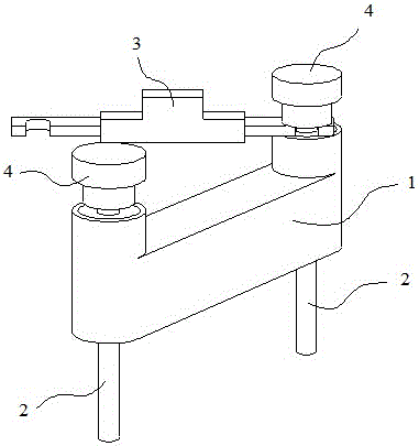
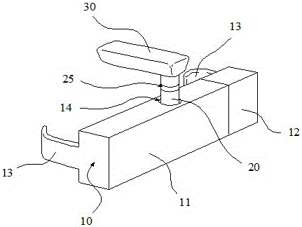
[0032] The invention provides a state monitoring terminal structure for an electrical protection pressure plate. image 3 A schematic diagram showing a specific implementation structure of the status monitoring terminal of the present invention. Such as image 3 As shown, the condition monitoring terminal has a strip-shaped terminal housing 10 as a whole, and the terminal housing 10 has a mounting structure so that it can be installed in parallel on the side of the insulating base of the electrical protection pressure plate. The middle part of the elongated terminal housing 10 has a vertically arranged guide chute 14 with an opening on the upper surface of the terminal housing. A sliding rod that can slide vertically up and down along the guide chute is inserted in the guide chute 14. 20, and the upper end of the sliding rod 20 protrudes from the opening of the guide chute 14. An operating handle 30 made of insulating material is fixedly disposed on the upper end of the slid...


PUM


Abstract

The invention provides a state monitoring terminal structure for the electric protection pressure plate, which can be conveniently installed on the side of the insulating base of the electric protection pressure plate, and can adjust the up and down position of the sliding rod in the guide chute by holding the operating handle The sliding position is used to set the working state of the condition monitoring terminal, which is convenient for installation and operation, and the matching structure between the guide chute and the sliding rod greatly improves the working stability of the condition monitoring terminal. In addition, through various optimized designs, Make the working status of the status monitoring terminal better correspond to the switching status of the electrical protection pressure plate, avoid causing the remote monitoring computer to make mistakes in the monitoring information of the switching status of the electrical protection pressure plate, and check the fault and work status settings for the operator The error provides convenience, and well solves the problems of poor working stability and inconvenient installation, use and operation of the state monitoring terminal in the prior art.

Description

technical field [0001] The invention relates to the technical field of substation equipment status monitoring, in particular to a status monitoring terminal structure for electrical protection pressure plates. Background technique [0002] Electrical protection pressure plates (also known as electrical protection connectors) are the most widely used in domestic protection devices because of the visibility of the connection and disconnection points after operation. At present, a large number of electrical protection pressure plates are installed on the protective screens of power plants and substations that have been put into operation. Due to the intuitive disconnection point, the operating personnel can judge the state of the relay protection device circuit, and provide maintenance and operation Provides great convenience. According to the position of the secondary circuit of the access protection device, the electrical protection pressure plate can be divided into two cat...

Claims


Application Information

Patent Timeline
Patent Type & Authority Patents(China)
IPC IPC(8): H02J13/00
CPCY04S40/126Y02E60/00
Inventor 高元生陈强熊小伏周岐杰郑昌圣
Owner DAZHOU POWER BUREAU SICHUAN ELECTRIC POWER
Why Eureka
Try Eureka