
Converter

A converter and direct current technology, applied in the field of converters, can solve problems such as low integration of converters, inconvenient maintenance, and large converter cabinet size, so as to facilitate on-site maintenance, reduce errors, and reduce failures rate effect

Inactive Publication Date: 2015-01-14
ZHUZHOU CSR TIMES ELECTRIC CO LTD
View PDF6 Cites 13 Cited by
  • Summary
  • Abstract
  • Description
  • Claims
  • Application Information

AI Technical Summary

Problems solved by technology

[0003] The integration level of existing converters is not high, usually only the power device part is integrated
In this way, when the existing converter is installed in the converter cabinet for use, it is necessary to configure additional peripheral circuit devices, resulting in an oversized converter cabinet and inconvenient maintenance

Method used


Image

  • Converter
  • Converter
  • Converter

Examples


Embodiment Construction

[0048] The implementation of the present invention will be described in detail below in conjunction with the accompanying drawings and examples, so as to fully understand and implement the process of how to apply technical means to solve technical problems and achieve technical effects in the present invention. It should be noted that, as long as there is no conflict, each embodiment and each feature in each embodiment of the present invention can be combined with each other, and the formed technical solutions are all within the protection scope of the present invention.

[0049] Also, in the following description, for purposes of explanation, numerous specific details are set forth in order to provide a thorough understanding of embodiments of the invention. It will be apparent, however, to one skilled in the art that the present invention may be practiced without the specific details or in the particular manner described.

[0050] In addition, the steps shown in the flow dia...


PUM


Abstract

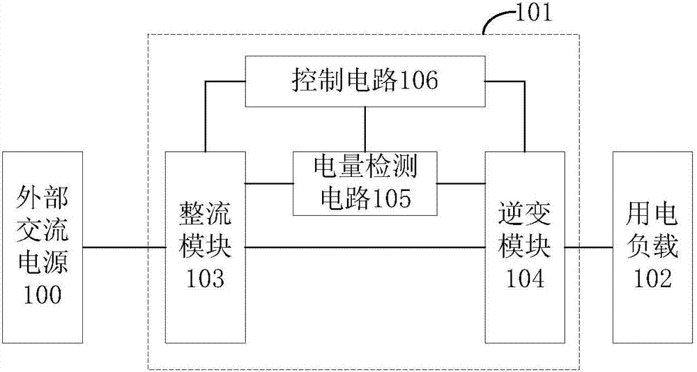
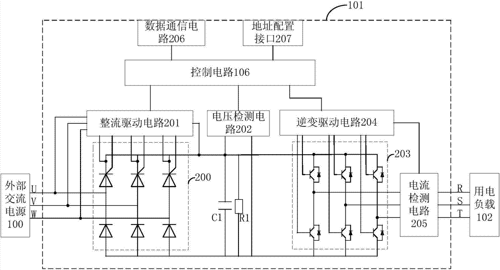
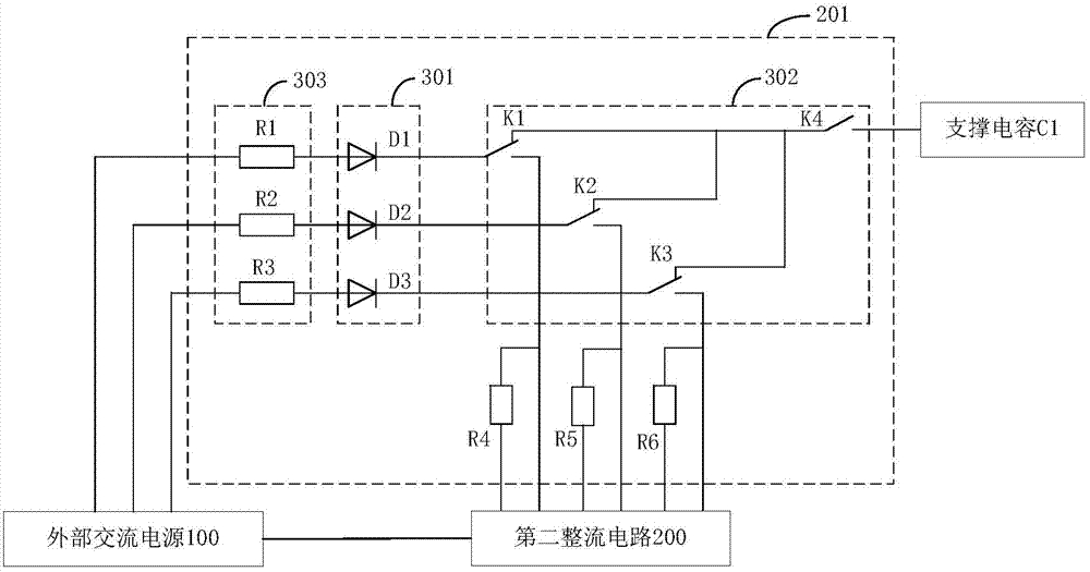
The invention discloses a converter. The converter comprises a rectifier module, an inversion module, an electric quantity detecting circuit and a control circuit, wherein the rectifier module is used for converting input first alternating current into first direct current and outputting the direct current, the inversion module is connected with the rectifier module and is used for converting the first direct current output by the rectifier module into second alternating current and outputting the second alternating current, the electric quantity detecting circuit is connected with the rectifier module and the inversion module and is used for detecting the electric quantity information of the rectifier module and the electric quantity information of the inversion module, and the control circuit is connected with the rectifier module, the inversion module and the electric quantity detecting circuit and is used for controlling the rectifier module according to a rectification signal generated by the received electric quantity information of the rectifier module and controlling the inversion module according to an inversion control signal generated by the electric quantity information of the inversion module. According to the converter, the integration level is high; due to the fact that the control circuit is integrated inside the converter and an extra control unit is not needed, the connection method is simplified, and the failure rate of the converter is reduced.

Description

technical field [0001] The invention relates to the technical field of power electronics, in particular to a converter. Background technique [0002] Converter power supply has the advantages of high efficiency, energy saving and low noise, so it is widely used in locomotive auxiliary power supply system. The converter is one of the core components of the auxiliary converter device. It contains many components and the interior space of the locomotive is small. This requires the converter to have the characteristics of compact structure and easy maintenance. [0003] The integration level of existing converters is not high, usually only the power device part is integrated. In this way, when the existing converter is installed in the converter cabinet for use, additional peripheral circuit devices need to be configured, resulting in an excessively large volume of the converter cabinet and inconvenient maintenance. [0004] Based on the above situation, there is an urgent nee...

Claims


Application Information

Patent Timeline
Patent Type & Authority Applications(China)
IPC IPC(8): H02M5/458
CPCH02M5/458H02M1/0009
Inventor 罗国永高路路刘长清徐文龙赵清良邹建军李强勤唐勇军
Owner ZHUZHOU CSR TIMES ELECTRIC CO LTD
Learn More