Hydraulic mounted plough

A technology of hydraulic suspension and ploughshares, which is applied to ploughs, agricultural machinery, and lifting devices of agricultural machinery, etc., can solve the problems of poor adaptability to the degree of soil softness and hardness, time-consuming and laborious, broken ploughshares, etc., and achieves consistent ridge depth, strong flexibility, Easy-to-use effects

Inactive Publication Date: 2015-01-21
张国军
View PDF5 Cites 5 Cited by
  • Summary
  • Abstract
  • Description
  • Claims
  • Application Information

AI Technical Summary

Problems solved by technology

However, the existing hanging plow has poor adaptability to the softness and hardness of the land. During the operation, if obstacles such as stones are encountered, they cannot be avoided in time, resulting in damage to the p

Method used


Image

  • Hydraulic mounted plough
  • Hydraulic mounted plough
  • Hydraulic mounted plough

Examples


Embodiment 1

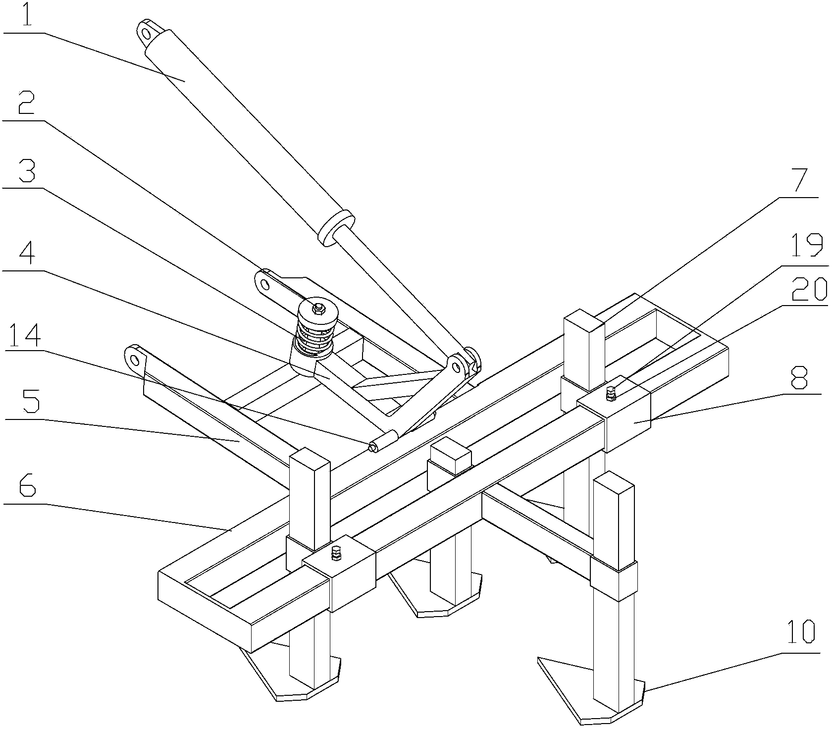
[0027] Such as figure 1 As shown, the present invention includes a lifting oil cylinder 1, an automatic lifting device 4, a traction support 5, a plowshare support 6 and a plowshare device, wherein the front end of the traction support 5 is hinged with the rear of the motor vehicle, and the rear end is connected with the plowshare support 6. The automatic lifting The device 4 is hinged on the traction bracket 5 , and one end is hinged to the output end of the lifting cylinder 1 . There are multiple plowshare devices installed on the plowshare bracket 6 . The lifting cylinder 1 is a two-way hydraulic cylinder, and is connected with a single-column hydraulic distributor through a hydraulic oil pipe. The traction support 5, the plowshare support 6 and the plowshare device are driven by the lifting cylinder 1 to rise or fall as a whole.

[0028] The automatic lifting device 4 comprises a V-shaped support, a screw rod 2, a spring 3, a limit block and a stop nut, wherein the screw ...

Embodiment 2

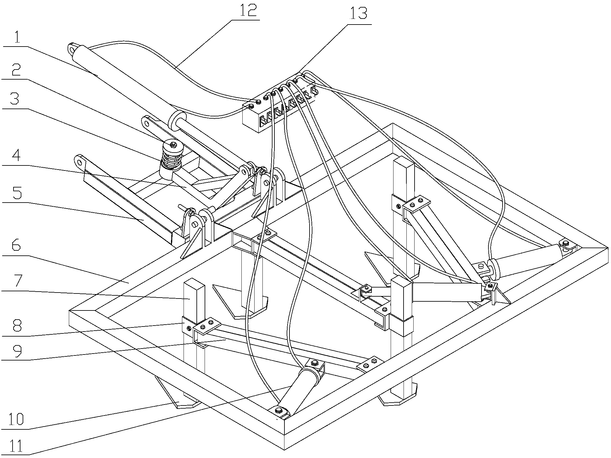
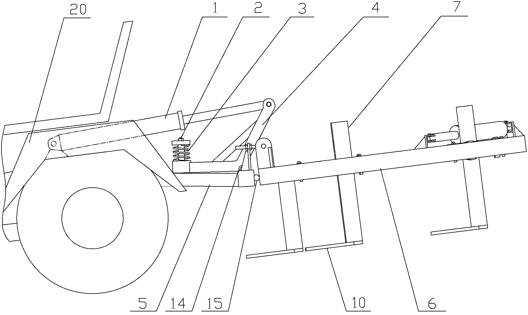
[0033] Such as Figure 2-5 As shown, the automatic lifting device 4 and the plowshare device of the present embodiment are the same as those of the first embodiment. The difference is that in this embodiment, the distance between the plowshares 10 is adjusted by the plowshare spacing adjustment mechanism, and a plowshare parallelism adjustment mechanism is provided between the traction bracket 5 and the plowshare support 6, which is used to adjust the parallelism between the plowshare support 6 and the ground , so that the heights of each plowshare 10 are equal, thereby ensuring that the plowing depth of each plowshare 10 is the same.

[0034] The plowshare spacing adjustment mechanism includes an adjustment arm 9 and an arm adjustment oil cylinder 11 . The plowshare device is hinged on the plowshare support 6 through the adjustment arm 9, the adjustment support arm 9 is hinged with the output end of the arm adjustment cylinder 11 installed on the plowshare support 6, and the...


PUM


Abstract

The invention relates to agricultural plough equipment, in particular to a hydraulic mounted plough. The hydraulic mounted plough comprises a lifting oil cylinder, an automatic lifting device, a traction support, a plough share support and plough share devices. The front end of the traction support is hinged to the tail of a locomotive, and the rear end of the traction support is connected with the plough share support. The automatic lifting device is hinged to the traction support, and one end of the automatic lifting device is hinged to the output end of the lifting oil cylinder. The multiple plough share devices are detachably installed on the plough share support, and the traction support, the plough share support and the plough share devices are driven by the lifting oil cylinder to integrally ascend or descend. The plough share devices are hinged to the plough share support through adjusting support arms, the adjusting support arms are hinged to the output ends of support arm adjusting oil cylinders installed on the plough share support, and the distance between the plough share devices is adjusted through driving of the support arm adjusting oil cylinders. The hydraulic mounted plough is simple in structure and convenient to operate and achieves the purposes of automatically adjusting the row spacing and avoiding obstacles.

Description

technical field [0001] The invention relates to an agricultural land cultivation equipment, in particular to a hydraulically suspended plow. Background technique [0002] In agricultural production, with the advancement and development of science and technology, my country has realized agricultural mechanization, and the hanging plow is a commonly used agricultural machine tool in agricultural production. However, the existing hanging plow has poor adaptability to the degree of softness and hardness of the land. During the operation, obstacles such as stones cannot be avoided in time, thereby causing damage to the plowshare. In addition, it is troublesome to adjust the depth of the plowshare and the distance between the ridges, and the operation needs to be done manually, which is time-consuming and laborious, and it is inconvenient to use. Contents of the invention [0003] In view of the above problems, the object of the present invention is to provide a hydraulic suspe...

Claims


Application Information

Patent Timeline
IPC IPC(8): A01B3/36A01B63/10A01B63/114
Inventor 张国军
Owner 张国军
Why Eureka
Try Eureka