Optical cable fish luring device and fishing method

A fiber optic cable and fish luring technology, which is applied in fishing, agricultural fishing, applications, etc., can solve the problems of limited fish luring range and immobile fish luring device, and achieve the effect of large fish luring range

Active Publication Date: 2015-01-21
瑞安市华盛水产有限公司
View PDF8 Cites 4 Cited by
  • Summary
  • Abstract
  • Description
  • Claims
  • Application Information

AI Technical Summary

Problems solved by technology

[0006] The object of the present invention is to provide an optical cable fish luring device and a fishing method that can guide fish to a predetermined

Method used


Image

  • Optical cable fish luring device and fishing method
  • Optical cable fish luring device and fishing method
  • Optical cable fish luring device and fishing method

Examples


Embodiment 1

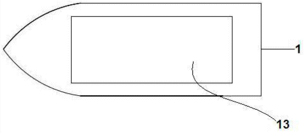
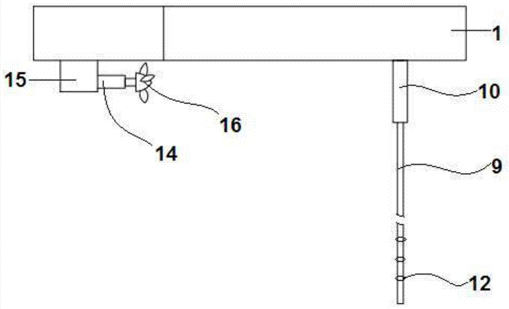
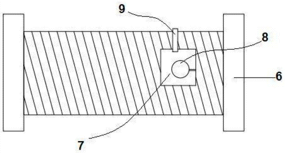
[0061] Such as figure 1 , 4 The illustrated embodiment is a kind of optical cable fish luring device, comprising a boat-shaped floating body 1, a power switch 24 arranged on the floating body, a controller 2 arranged in the front of the floating body, a wireless transmitter 17, a steering motor 3, and a Beidou locator 4. The first storage battery 5. The storage battery for power supply, which is located in the rear of the floating body such as image 3 The retractor 6 shown;

[0062] Such as Figure 4 The shown light intensity adjustment device 20, wireless receiver 18, microprocessor 19, second memory 23, such as image 3 The airtight cavity 7 shown is arranged on the illuminant 8 in the airtight cavity; the waveform used to control the light intensity variation is stored in the second memory, the controller reads the waveform signal in the second memory, and the data acquisition card collects the waveform signal The waveform signal is output to the power amplifier, and t...

Embodiment 2

[0079] Embodiment 2 includes all the structure and method parts of the embodiment, and also includes a vibration sensor 11 located in the floating body, and the vibration sensor is electrically connected to the controller; it also includes the following steps:

[0080] Step 610, the standard signal-to-noise ratio SNR is set in the memory 标准 , the rotation speed C1 of the propeller motor is 30 rpm, and the rotation speed C2 is 50 rpm; during the movement of the optical cable fish luring device, the vibration sensor detects the vibration signal of the floating body, and the controller selects a detection signal within 4 minutes from the current time. Spect(t);

[0081] Step 620, data processing:

[0082] The controller inputs the detection signal Spec(t) into a stochastic resonance model Among them, V(x, t) is the potential function, x(t) is the Brownian motion particle trajectory function, a, b are the set constants, ξ(t) is the external noise, D is the external noise intens...


PUM


Abstract

The invention discloses an optical cable fish luring device and a fishing method. The optical cable fish luring device comprises a ship-shaped floater, a power switch, a controller, a wireless transmitter, a helm steering motor, a Beidou locator, a first storage device, a storage battery, a reeling device, a light intensity adjusting device, a wireless receiver, a microprocessor, a second storage device, a closed cavity, an illuminant, an optical cable, a helm, a propeller motor and a propeller. The power switch is arranged on the floater, the controller, the wireless transmitter, the helm steering motor, the Beidou locator, the first storage device and the storage battery are arranged in the front portion of the floater, the storage battery is used for supplying power, the reeling device is arranged in the rear portion of the floater, the light intensity adjusting device, the wireless receiver, the microprocessor, the second storage device and the closed cavity are arranged in the reeling device, the illuminant is arranged in the closed cavity, one end of the optical cable extends into the closed cavity and is connected with the closed cavity in a closed mode, the helm is arranged on the lower surface of the floater, and the propeller motor and the propeller are arranged below the floater. The optical cable fish luring device has the advantages of being large in fish luring range, capable of bringing convenience for purse seine fishing, good in stability and not prone to be turned over.

Description

technical field [0001] The invention relates to the technical field of fishing, in particular to an optical cable fish luring device and a fishing method capable of guiding fish to swim to a predetermined positioning point. Background technique [0002] Although the phototaxis response of fish is affected by many internal and external factors and produces a variety of performances, phototaxis is one of its abilities to adapt to the living environment. [0003] The light intensity at which the maximum phototaxis rate is generated in the phototaxis reaction of fish is called the suitable illuminance. The fish gathering technology in light fishing production is based on the appropriate illumination. In the underwater light field of the same light, different phototaxis fish will gather in their own unique suitable illumination area; if the illumination intensity of the light increases or decreases, the fish will follow the movement of the appropriate illumination and float up. ...

Claims


Application Information

Patent Timeline
IPC IPC(8): A01K71/00A01K79/00
CPCA01K71/00A01K79/00Y02P60/60
Inventor 朱文斌陈峰王洋张洪亮周永东徐汉祥王忠明
Owner 瑞安市华盛水产有限公司
Why Eureka
Try Eureka