
Lever manipulator

A manipulator and rod-type technology, applied in the field of electronic control, can solve problems such as reliability decline, and achieve the effect of making up for excessive use of components, simple structure, and easy production and use

Inactive Publication Date: 2015-01-21
过志浩
View PDF0 Cites 1 Cited by
  • Summary
  • Abstract
  • Description
  • Claims
  • Application Information

AI Technical Summary

Problems solved by technology

[0003] The object of the present invention is to provide a stick manipulator that solves the problem of reduced reliability by reducing the use of components

Method used


Image

  • Lever manipulator
  • Lever manipulator
  • Lever manipulator

Examples


Embodiment Construction

[0018] The present invention will be described in further detail below in conjunction with the accompanying drawings.

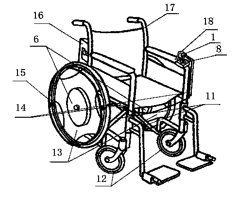
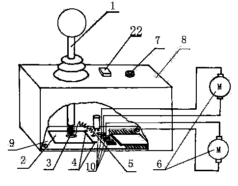
[0019] In the figure, the joystick 1 , the power socket 7 and the indicator 22 are respectively arranged on the controller box 8 . The controller box 8 is fixed on the vehicle frame 17 of the wheelchair, and the battery 16 is also fixed on the vehicle frame 17 of the electric wheelchair, and is connected with the control circuit by the power socket 7 . The brake handle 18 is fixed on the operating handle 1 and controls the brake 14. One end of the control handle near the resistor 2 is provided with a conductive contact 3 . Two output terminals 4 on the resistor 2 are connected to the modulation circuit 20 in the control circuit 19, the modulation circuit 20 is connected to the main circuit 21 of the control circuit 19, and a lead 5 is connected to the conductive contact with the main circuit 21, and the two motors 6 It is connected to the control circ...


PUM


Abstract

The invention discloses a lever manipulator which comprises a control handle, a sensing element and a sensing source. The lever manipulator is characterized in that at least one sensing element and at least one sensing source are included, the sensing element, the sensing source and the control handle together form a device which outputs two change signals by adjusting the positions of the sensing source and the sensing element. According to the lever manipulator, fewer elements are used, and the defect that reliability is reduced is overcome.

Description

technical field [0001] The invention relates to electronic control technology, especially to electric manipulators. Background technique [0002] At present, the adjustment method of the known rod manipulator is relatively complicated, which reduces the reliability. Contents of the invention [0003] The object of the present invention is to provide a stick manipulator which solves the problem of reduced reliability by reducing the use of components. The invention adopts the following technical solutions. [0004] The rod-type manipulator of the present invention includes a joystick, a sensing element, and a sensing source, and is characterized in that: it is composed of at least one sensing element, at least one sensing source and the joystick, and outputs two change signals by adjusting the positions of the sensing source and the sensing element installation. [0005] The present invention can also use a resistance element as an inductive element, and the inductive s...

Claims


Application Information

Patent Timeline
Patent Type & Authority Applications(China)
IPC IPC(8): A61G5/10A61G5/04
Inventor 不公告发明人
Owner 过志浩
Learn More