Clutch master cylinder body piston hole drilling clamp

A clutch master cylinder and piston hole technology, which is applied in the field of machinery manufacturing equipment, can solve the problems of heavy labor, affect processing quality, and low work efficiency, and achieve the effects of saving labor, saving working time, and improving work efficiency.

Inactive Publication Date: 2015-01-21
WUHU HENGHAO MACHINERY MFG
View PDF6 Cites 23 Cited by
  • Summary
  • Abstract
  • Description
  • Claims
  • Application Information

AI Technical Summary

Problems solved by technology

[0003] At present, the technology and equipment for processing the clutch master cylinder emerge in endlessly, but when processing the piston hole of the clutch master cylinder, the combined processing method of ordinary drilling machine and traditional drilling jig is often used. The clamping method of the traditional drilling jig is manual. Clamping, which will not only affect the processing quality, but also lower work efficiency and greater labor workload

Method used


Image

  • Clutch master cylinder body piston hole drilling clamp
  • Clutch master cylinder body piston hole drilling clamp
  • Clutch master cylinder body piston hole drilling clamp

Examples


Embodiment Construction

[0016] In order to make the technical means, creative features, goals and effects achieved by the present invention easy to understand, the present invention will be further elaborated below.

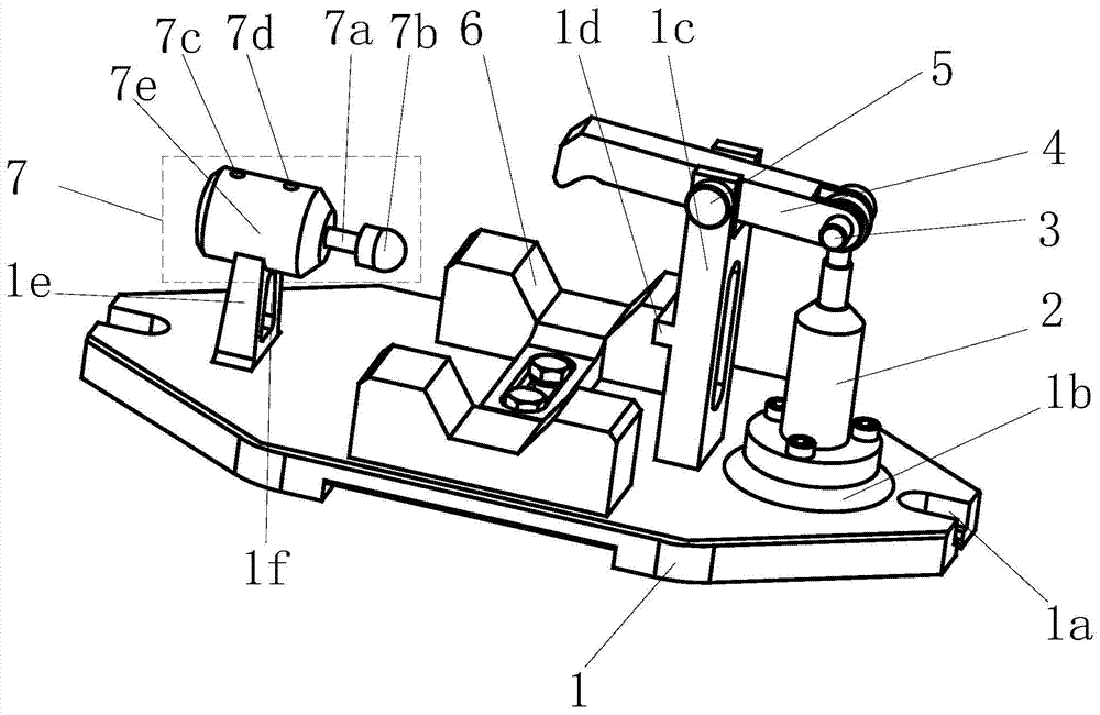
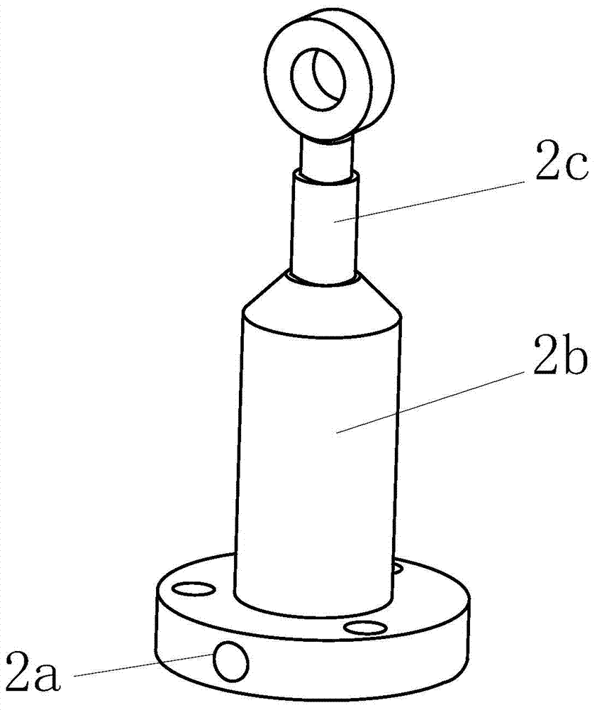
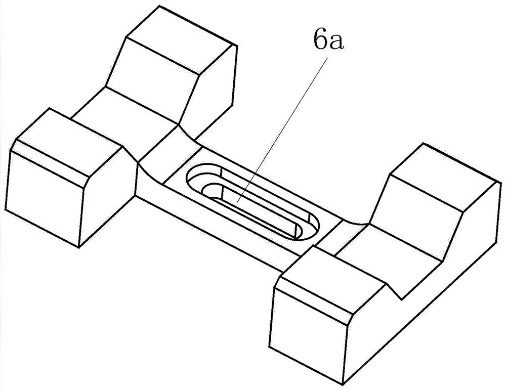
[0017] Such as Figure 1 to Figure 4 Shown, a kind of clutch master cylinder piston hole drilling jig comprises base 1, No. 1 hydraulic cylinder 2, No. 1 pin 3, pressure plate 4, No. 2 pin 5, V-shaped positioning block 6 and No. 2 hydraulic cylinder 7. Both left and right ends of the base 1 are provided with lugs 1a, which are used for the connection between the fixture and the workbench of the machine tool. The boss 1b is provided with threaded holes on the circular boss 1b, the left side of the circular boss 1b is provided with a support frame 1c, the middle part of the support frame 1c is provided with a positioning block 1d, and the top of the support frame 1c is provided with Through holes, the left end of the upper surface of the base 1 is provided with a trapezoidal support plat...


PUM


Abstract

A clutch master cylinder body piston hole drilling clamp comprises a base, a first hydraulic cylinder, a first pin, a pressing plate, a second pin, a V-shaped locating block and a second hydraulic cylinder. Lug seats are arranged at the left end and the right end of the base, a round boss is arranged at the right end of the upper surface of the base, a supporting frame is arranged on the left side of the round boss, a trapezoid supporting table is arranged at the left end of the upper surface of the base, the first hydraulic cylinder is fixed to the round boss of the base through screws, the tail end of the pressing plate is hinged to one end of a first piston of the first hydraulic cylinder through the first pin, the middle of the pressing plate is hinged to the supporting frame through the second pin, the V-shaped locating block is located between the supporting frame and the trapezoid supporting table, and is fixed to the base through bolts, and the second hydraulic cylinder is welded to the trapezoid supporting table. Fast clamping can be achieved, work efficiency is greatly improved, machining precision is guaranteed, meanwhile, labor force is saved, and the investment of production cost is lowered.

Description

technical field [0001] The invention relates to the technical field of mechanical manufacturing equipment, in particular to a jig for drilling piston holes in a pump body of a clutch master cylinder. Background technique [0002] The clutch is located in the flywheel housing between the engine and the gearbox, and the clutch assembly is fixed on the rear plane of the flywheel with screws, and the output shaft of the clutch is the input shaft of the gearbox. During the driving process of the car, the driver can step on or release the clutch pedal as needed to temporarily separate and gradually engage the engine and the transmission, so as to cut off or transmit the power input from the engine to the transmission. The clutch master cylinder is the part connected to the clutch pedal and connected to the clutch booster through the oil pipe. Its function is to collect pedal stroke information, and the clutch is separated under the action of the booster. Therefore, the clutch mas...

Claims


Application Information

Patent Timeline
Patent Type & Authority Applications(China)
IPC IPC(8): B23Q3/08
CPCB23Q3/082B23Q3/062
Inventor 袁道华
Owner WUHU HENGHAO MACHINERY MFG
Why Eureka
Try Eureka