Three-dimensional engraving machine

A three-dimensional engraving machine and frame technology, applied in the field of machinery, can solve the problems of complex connection and coordination, loose tools, and many parts, etc., and achieve the effects of simple connection and coordination, improved engraving accuracy, and stable state.

Active Publication Date: 2017-08-25
台州耐科兴智能装备有限公司
View PDF1 Cites 0 Cited by
  • Summary
  • Abstract
  • Description
  • Claims
  • Application Information

AI Technical Summary

Problems solved by technology

[0004] But in this three-dimensional engraving machine, the tool rack is first set on the vertical drag block, the vertical drag block is set on the horizontal drag plate, and the horizontal drag plate is set on the beam. Obviously, in this three-dimensional engraving machine, the tool rack and the beam The connection and cooperation relationship between them is relatively complicated, and there are many parts between the tool holder and the beam, which leads to the fact that the tool holder cannot be placed on the beam more stably. That is to say, when the tool on the tool holder rotates, the tool is easy to The fit between the parts between the tool holder and the beam is not tight and loose, which leads to the low engraving accuracy of the three-dimensional engraving machine. No matter what, under the same conditions, the cumulative error of the cooperation of multiple parts is always greater than zero Cumulative errors of components

Method used


Image

  • Three-dimensional engraving machine
  • Three-dimensional engraving machine
  • Three-dimensional engraving machine

Examples


Embodiment 1

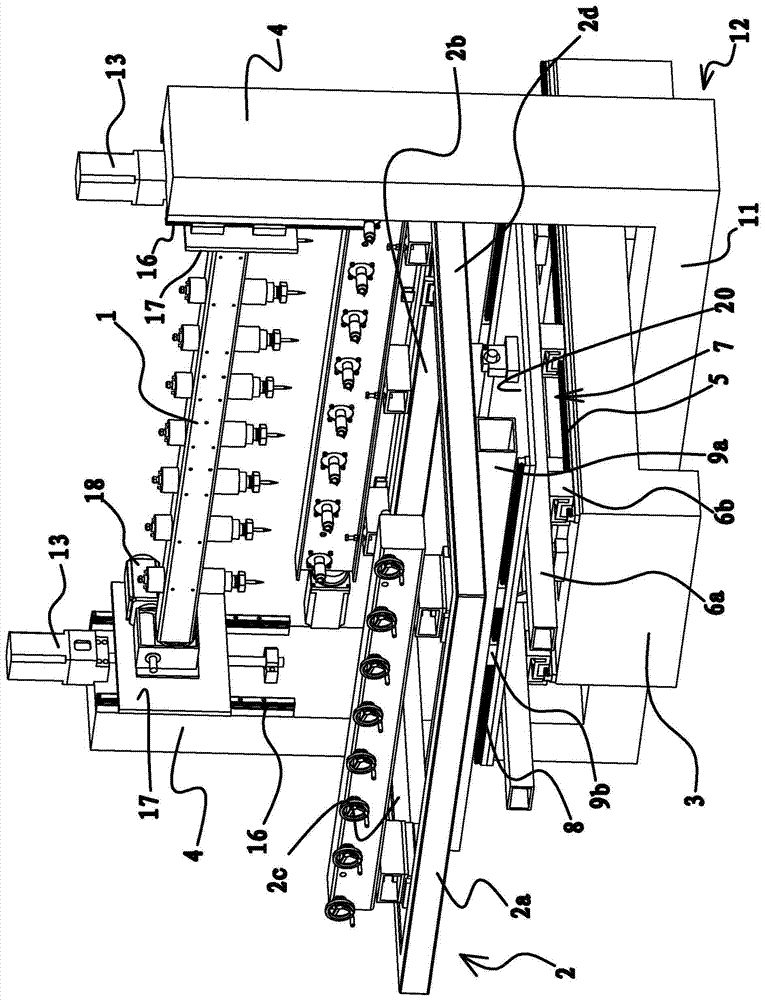
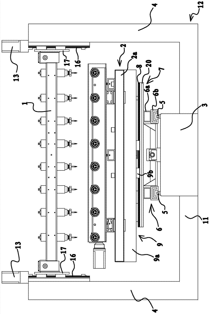
[0033] Such as figure 1 As shown, the three-dimensional engraving machine includes a frame 12 and an engraving platform 2 arranged on the frame 12 . Wherein, the frame 12 includes a base 3 and columns 4 arranged on both sides of the base 3, a bottom beam 11 is provided on the bottom side of the base 3, the base 3 is overlapped on the upper side of the bottom beam 11, and two columns 4 are fixed on the bottom beam 11. ends. A tool holder 1 for installing a tool is provided between the upper ends of the two columns 4 , and a lifting motor 13 for driving the tool holder 1 to move up and down is provided between the column 4 and the tool holder 1 . Specifically, vertical guide rails are fixed on the two columns 4 , and both ends of the tool holder 1 are co-located on the guide rails of the column 4 . The column 4 is provided with a motor, and the motor drives the tool holder 1 to move up and down along the direction of the guide rail on the column 4 through the cooperation of th...

Embodiment 2

[0048] This embodiment is substantially the same as Embodiment 1, the difference is that in this embodiment, if Figure 4 As shown, in order to facilitate the collection and centralized treatment of cutting chips during the engraving process, so that the production environment is more tidy during the engraving process, the bottom of the engraving platform 2 is fixed on the bottom of the engraving platform 2 for receiving cutting chips. Chip board 19.


PUM


Abstract

The invention provides a three-dimensional engraving machine, which belongs to the technical field of machinery. It solves the problem of low engraving precision of existing three-dimensional engraving machines. The engraving machine includes a frame and an engraving platform arranged on the frame. A tool rack for installing knives is arranged above the engraving platform. The frame includes a base and columns arranged on both sides of the base. Between the column and the tool rack An elevating motor for driving the tool holder to move up and down is provided between them, a longitudinal motor is provided on the base to drive the driving plate to reciprocate horizontally and longitudinally, and a transverse motor is provided on the driving plate to drive the workbench to reciprocate horizontally and horizontally. In the engraving machine, the connection relationship between the tool holder and the column is relatively simple, and the tool holder is relatively stable when moving, which improves the engraving precision.

Description

technical field [0001] The invention belongs to the technical field of machinery and relates to a three-dimensional engraving machine. Background technique [0002] From the processing principle, engraving is a combination of drilling and milling. It has a wide range of applications, including woodworking engraving machines, laser engraving machines, advertising engraving machines, jade engraving machines, stone engraving machines, cylindrical engraving machines, etc. Three-dimensional engraving machine is an industry classification of engraving machine. It is a new type of CNC equipment in recent years. Its working principle is very similar to that of CNC milling machine. By controlling the three-axis movement, the effect of automatic engraving can be achieved. The application range of three-dimensional engraving machine It is so extensive that it even replaces the manual engraving technology, laying the foundation for mass and rapid production of products. [0003] For ex...

Claims


Application Information

Patent Timeline
Patent Type & Authority Patents(China)
IPC IPC(8): B44B1/00B44B1/06
Inventor 吴善旺
Owner 台州耐科兴智能装备有限公司
Why Eureka
Try Eureka