Full-automatic automobile washing device

A fully automatic, spray device technology, applied in the direction of vehicle exterior cleaning devices, etc., can solve the problems of weakening the spray head flushing effect, low work efficiency, reasonable lifting, etc., to solve the problem of serious waste of water and electricity, high car washing efficiency, and clean car washing. Effect

Active Publication Date: 2015-01-21
绍兴市中令汽车服务有限公司
5 Cites 25 Cited by

AI-Extracted Technical Summary

Problems solved by technology

However, this device can only detect the distance between the spray rack and the side of the vehicle body, so although the spray rack can move longitudinally, laterally, and rotationally, it cannot be controlled and reasonably raised and lowered in the height direction to adapt to large changes in the height of the vehicle body , so that the high top spray bar is too ...

Method used

Because the action distance of each spray bar and the automobile body is controlled within a reasonable range, so the spraying effect is more ideal, taking the movement of the crossbeam from the middle part of the vehicle body to the front of the car as an example, the height of the vehicle body gradually increases along with the windshield and the engine cover. As it is lowered, the top spray bar is also gradually lowered, and the entire spray device has realized close-range motion control, thereby greatly improving the cleaning effect.
The present invention is aimed at the scientific requirement of high-pressure water cleaning to action distance, has solved the vehicle body height measurement problem, and has adopted ...

Abstract

A full-automatic automobile washing device comprises a spraying device. The spraying device comprises a top spraying rod and vertical spraying rods. The left vertical spraying rod and the right vertical spraying rod are each provided with a plurality of shower nozzles in the vertical direction, and the nozzles of the left vertical spraying rod are opposite to the nozzles of the right vertical spraying rod. Shower nozzles with nozzles facing downwards are distributed on the top spraying rod. The spraying rods are each provided with a switching mechanism, and the shower nozzles can be connected with a high-pressure water source and a high-pressure air source. The switching mechanisms can be in linkage with an output shaft of a switching motor. The top spraying rod, the left vertical spraying rod and the right vertical spraying rod are connected with a beam which is arranged on a guide rail in the manner of sliding forwards and backwards through a driving motor, the top spraying rod can be arranged on the beam in an ascending and descending mode through a lifting motor, the left vertical spraying rod and the right vertical spraying rod can be connected with the beam in the manner of moving left and right through respective motors, and the beam is provided with a detecting device which can detect the size of an automobile body. The full-automatic automobile washing device is ingenious and reasonable in structure, high in automation degree and more complete in function, effectively solves the problems of an existing automobile washing machine, and is a very practical automobile washing device.

Application Domain

Technology Topic

Image

  • Full-automatic automobile washing device
  • Full-automatic automobile washing device
  • Full-automatic automobile washing device

Examples

  • Experimental program(1)

Example Embodiment

[0029] The present invention will be described in further detail below in conjunction with the embodiments of the drawings.
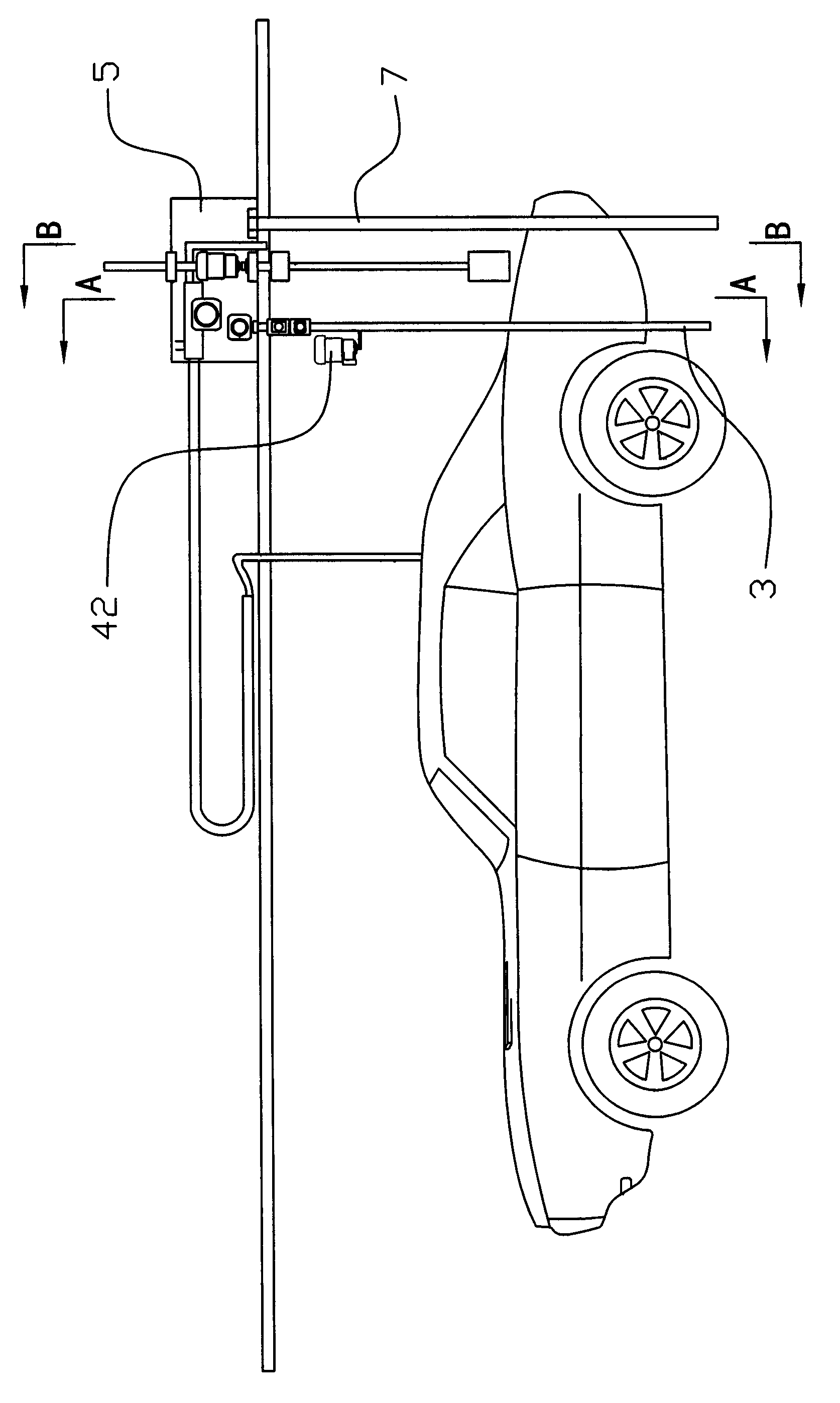
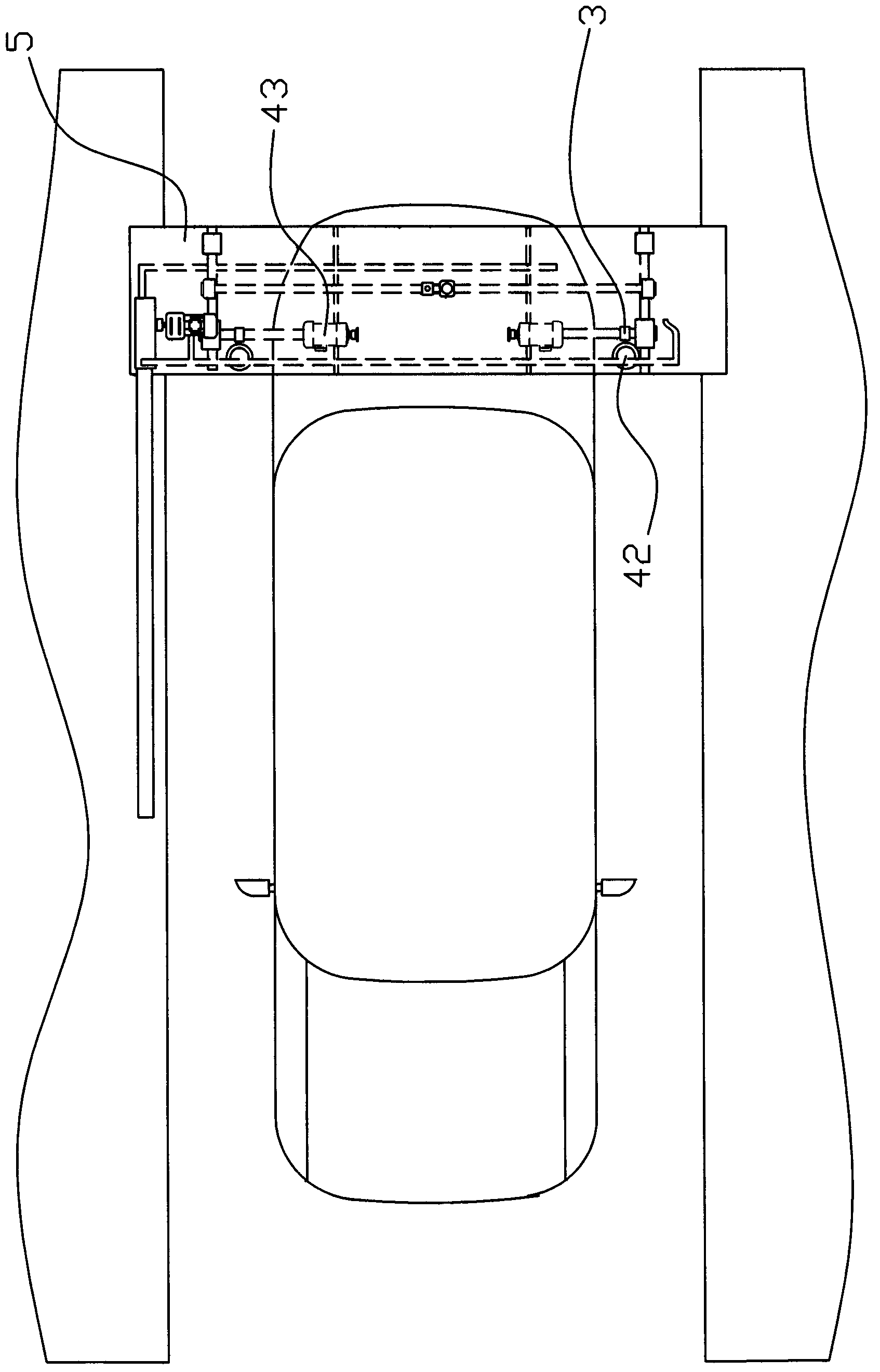
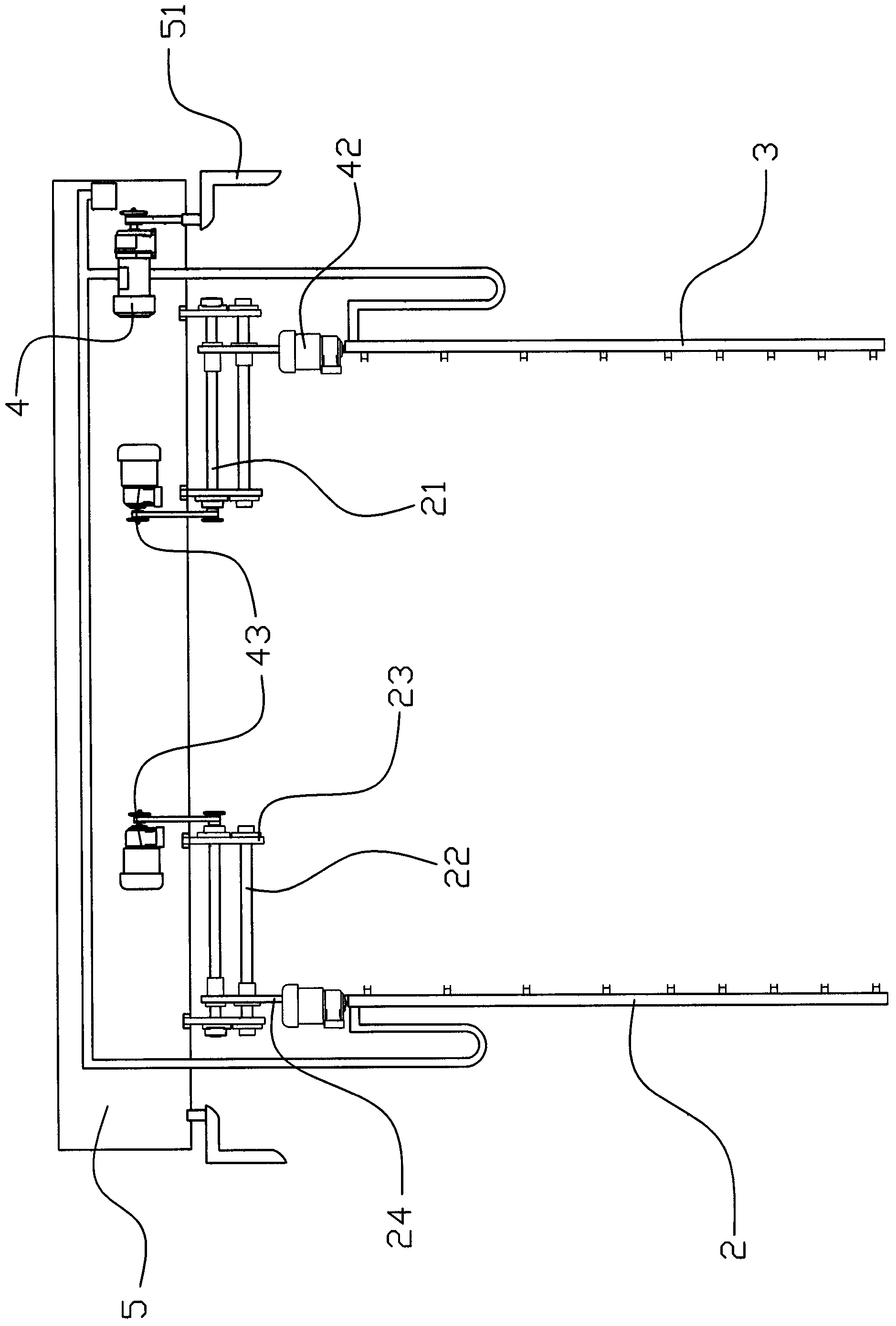
[0030] Such as Figure 1 to Figure 14 As shown, the fully automatic car washing device of this embodiment includes a spray device. The spray device includes a horizontally arranged top spray bar 1 and a left and right vertical spray bar, a left vertical spray bar 2 and a right vertical spray bar. A plurality of spray heads 6 are distributed up and down in the spray bar 3, and the nozzles of the left and right vertical spray bars 2, 3 are arranged oppositely. The spray head 6 with downward nozzles is distributed on the top spray bar 1. The rod 2 and the right vertical spray rod 3 and the top spray rod 1 are respectively provided with a switching mechanism that enables the nozzle 6 to spray or spray water. The left and right vertical spray rods 2, 3 and the nozzle 6 on the top spray rod 1 are respectively It can be connected with a high-pressure water source and a high-pressure air source. The switching mechanism is linked with the output shaft of the switching motor 42. The top spray rod 1 and the left and right vertical spray rods 2, 3 are respectively slidable forward and backward through the drive motor 4. The crossbeam 5 on the guide rail 51 is connected, and the top spray bar 1 is arranged on the crossbeam 5 so that it can be lifted up and down by the lifting motor 41, and the left and right vertical spray bars 2, 3 are respectively connected to the crossbeam 5 so as to move left and right by their respective motors. Connected, and is provided with a detection device capable of detecting the size of the vehicle body on the beam 5. The lifting motor 41, the switching motor 42, the electric motor, the driving motor 4, the detection device and the solenoid valve switch that controls the high-pressure air source and the high-pressure water source are connected to The program control system is connected. The specific structure in which the left and right vertical spray rods 2, 3 can be connected to the beam 5 so that they can move left and right through their respective motors is as follows: on the left and right sides of the beam 5 are respectively provided with a screw 21 and a guide rod 22 that are parallel up and down. The guide rod 22 is located below the screw 21, and the two ends of the screw 21 and the guide rod 22 are respectively connected to the corresponding positions of the bottom of the cross beam 5 through respective fixed rods 23. The left and right vertical spray rods 2, 3 The upper part is respectively connected to the lower end of the respective connecting plate 24. The top of the connecting plate 24 is connected with a nut sleeve that can move left and right along the rotation of the screw 21. The middle part of the connecting plate 24 is respectively provided with a corresponding guide The rod 22 has a guide hole that can move left and right along the guide rod 22, and the screw rods 21 are respectively connected with corresponding screw motors 43 fixed on the beam 5. The specific structure of the top spray bar 1 which can be raised and lowered on the beam 5 through the lifting motor 41 is as follows: on the left and right sides of the beam 5 located behind or in front of the fixed rod 23, two parallel and lying on the same plane extend downward. The vertical guide rod 11, the top spray rod 1 is fixed to the upper sliding rod 13 through the connecting rod 12, and the two ends of the sliding rod can be moved up and down along the corresponding vertical guide rod 11 through sliding sleeves. On the vertical guide rod 11, it is movably connected to the lower end of the driving screw 14 at the middle of the sliding rod 13. The upper end of the driving screw 14 passes through the nut provided on the beam 5 and is fixed on the beam 5 for lifting The output shaft of the motor 41 is linked.
[0031] The detection device includes two detection rods 7, a detector capable of measuring the height of the vehicle body and the left and right positions of the vehicle body. One of the detection rods 7 is vertically fixed on the left end of the beam 5, and the other is vertically fixed on the right end of the beam 5 , The left and right detection rods are respectively installed with detectors that can adjust the left and right vertical spray rods 2, 3 to move left and right, and the bottom surface of the beam 5 is installed with a detector that can adjust the height of the top spray rod 1. Connect with the program control system through wires. The detector is an ultrasonic ranging sensor, a laser ranging sensor or an infrared ranging sensor.
[0032] The switching mechanism includes a cylindrical tube 8. The cylindrical tube 8 and the inner wall of the corresponding spray rod are arranged to be relatively rotatable and sealed with each other. The cylindrical tube 8 is fixed on the end of the corresponding spray rod to drive the cylindrical tube. The output shaft of the rotating switching motor 42 is linked with each other. On the circumferential surface of the cylindrical tube 8 are distributed vent holes 82 and liquid holes 81 that can communicate with the inner cavity of the cylindrical tube 8. When the cylindrical tube 8 rotates At this time, the vent hole 82 and the liquid hole 81 can communicate with the inner cavity of the corresponding nozzle 6 respectively. The switching motors of the left and right vertical spray rods are respectively fixed on the tops of the left and right vertical spray rods. The cylindrical tubes 8 in the inner cavities of the left and right vertical spray rods 2, 3 are arranged with vent holes 82 and vents arranged vertically. The liquid holes 81, the vent holes 82 are arranged in a row vertically distributed up and down, and the liquid holes 81 are arranged in multiple rows vertically distributed up and down. When the cylindrical tube 8 is rotated to the set position, the corresponding row of vent holes The liquid holes 81 can be respectively communicated with the inner cavity of the corresponding nozzle 6, and the liquid holes 81 and vent holes 82 that do not correspond to the rows cannot communicate with the inner cavity of the nozzle 6 and are in a closed state. When the cylindrical tube 8 is rotated to the setting When the vent holes 82 at the corresponding positions are connected to the inner cavity of the corresponding nozzle 6, the liquid hole 81 cannot communicate with the inner cavity of the nozzle 6 and is in a closed state. A "匚" shape is fixed on the crossbeam with a high-pressure water source. Or a conveying pipe connected with a high-pressure gas source, one end of the conveying pipe is connected to the upper part of the left vertical spray bar 2, and the other end of the conveying pipe is connected to the upper part of the right vertical spray bar 3, in the middle of the conveying pipe A through hole that can communicate with a high-pressure water source or a high-pressure air source through a hose is provided. The plurality of rows are three rows. The number of liquid holes 81 in the first row of liquid holes 81 corresponds to the number of nozzles 6 in the vertical spray bar, and the number of liquid holes 81 in the second row is less than the number of nozzles 6 in the vertical spray bar. The number of nozzles from the bottom to the top of the vertical spray bar are aligned. The number of liquid holes 81 in the third row is less than the number of nozzles 6 in the vertical spray bar. The number of nozzles between the bottom and the middle of the vertical spray bar is 2 The cylindrical pipe 8 at the position of the three nozzles 6 does not have a through hole 81. One end of the cylindrical tube in the top spray rod extends from one end of the top spray rod to be linked with the output shaft of the switching motor 42 fixed at the end of the top spray rod. The cylindrical tube located in the inner cavity of the top spray rod 1 8 are distributedly arranged with vent holes 82 and liquid holes 81, the vent holes 82 are arranged at left and right intervals, and the liquid holes 81 are also arranged at left and right intervals. When the cylindrical tube 8 is rotated to the set position The corresponding liquid holes 81 can be respectively communicated with the inner cavity of the corresponding nozzle 6, and the non-corresponding vent holes 82 cannot communicate with the inner cavity of the nozzle 6 and are in a closed state. When the cylindrical tube 8 is rotated to the set position When the air holes 82 are respectively communicated with the inner cavity of the corresponding spray head 6, the through-liquid hole 81 cannot communicate with the inner cavity of the spray head 6 and is in a closed state. The top surface of the middle position of the top spray rod 1 is provided with a soft The through hole that the pipe communicates with the high-pressure water source or the high-pressure gas source. The specific structure connecting the left and right sides of the conveying pipe with the corresponding upper parts of the left and right vertical spray rods 2 and 3 is as follows: the upper circumferential surfaces of the left and right cylindrical tubes 8 in the left and right vertical spray rods 2, 3 are respectively provided with annular cavities 84. At the bottom of the annular cavity 84 are respectively provided with 1 to 3 perforations 83 communicating with the inner cavity of the cylindrical tube 8, and the annular cavity 84 is respectively communicating with corresponding outlets at both ends of the conveying pipe.
[0033] Hereinafter, the present invention will be further explained:
[0034] The object of the present invention is to provide a brushless car washing machine that can achieve close cleaning of the top spray bar and the upper surface of the vehicle body, the left and right vertical spray bars and the side of the vehicle body, and the time is shorter. As we all know, the cleaning effect of the high-pressure water jet is directly related to the working distance. In actual work, after the high-pressure water jet comes out of the nozzle, it is appropriate that the distance from the surface to be acted on is about 25 cm, and the impact force will attenuate if it is farther, and the ideal high-pressure cleaning effect cannot be achieved. If a car washing machine is designed to wash 2 meters high cars, and the height of the bonnet of the car being washed is 85 cm, the high-pressure water from the nozzle of the top spray rod will be the end of the force when it reaches the upper surface of the car body. The cleaning effect is very unsatisfactory, and the energy consumption is greatly increased. In particular, if a high-pressure air nozzle is installed on the top spray rod to dry the surface of the car body, because the air jet comes out of the nozzle, its attenuation is much faster than the water jet, and a fixed top spray rod must be used to blow It is not technically feasible to dry the water stains on the upper surface of the car body.
[0035] In order to keep the top spray rod and the left and right vertical spray rods at a proper distance from the body, it is necessary to know the contour curve data such as the height of the car. Specifically, the vehicle height value at any cross section of the vehicle body, the minimum distance between the two sides of the vehicle body at that section and the suspension brackets on both sides must be known, and the position of the top spray bar and the left and right vertical spray bars must be effectively measured and controlled, and The application of these data must be based on the position of the beam at the time of measurement, combined with the specific location of the vehicle parked, and calculated to obtain the position data of the beam relative to the vehicle being cleaned.
[0036] The invention uses the cooperation of the detector and the program control system to measure and determine the actual position of the crossbeam, provide reference coordinates for the measurement and application of the body contour data, and measure the positions of the top spray bar, the left vertical spray bar, and the right vertical spray bar. The movement direction and movement distance are calculated by the pulse value of the stepping motor, and the movement control instruction is issued by the program control system. Among them, the controller can be an ultrasonic ranging sensor, a laser ranging sensor or an infrared ranging sensor.
[0037] Take the cleaning process of the car washing machine (that is, the car washing device, the same below) from the rear of the car to the front of the car as an example.
[0038] First, the beam drives the detector to run above the car to measure the body contour data. The program control system stores these values. According to the set cleaning distance requirements of each spray bar from the body surface, the program control system calculates the top spray bar, The movement position values ​​that the left and right vertical spray rods should reach. When the car washing machine moves from the rear of the car to the front of the car, the driving motor drags the beam to move forward as a whole. At different body positions, press the corresponding The control of the body contour of the vehicle requires motion instructions, and the corresponding motors drive the top spray bar, the left vertical spray bar, and the right vertical spray bar to reach the designated positions, so that the entire spray device and the upper part of the vehicle and the two sides of the body are Keep a reasonable distance, and working media such as high-pressure water and car wash fluid are sprayed to the body from the nozzle of each spray rod under the control of the program control system to achieve the ideal purpose of decontamination and cleaning of the vehicle.
[0039] Because the effective distance between each spray rod and the car body is controlled within a reasonable range, the spraying effect is more ideal. Take the movement of the beam from the middle of the car body to the front of the car as an example. The height of the car body gradually decreases with the windshield and engine cover. The spray bar also gradually drops, and the entire spray device realizes close-range motion control, which greatly improves the cleaning effect.
[0040] In the above embodiments, if the liquid working medium is changed to compressed air and the water spray head is changed to an air spray head, the spray device is an air drying device, and the corresponding body contour detection and the control and working modes of each movement mechanism are completely the same.
[0041] The program control system for motors, sensors and motion control adopted by the present invention is a mature and well-known technology, and will not be described in detail here.
[0042] In addition, the differences of the following various solutions (including but not limited to the following situations) are all within the intention of the present invention:
[0043] 1) The driving motors of the top spray bar, left vertical spray bar and right vertical spray bar adopt servo motors;
[0044] 2) The driving motor of the beam adopts stepping motor or servo motor;
[0045] 3) There can also be multiple top spray bars, left vertical spray bars, and right vertical spray bars.
[0046] The invention addresses the scientific requirements of high-pressure water cleaning for the working distance and solves the problem of measuring the height of the vehicle body. On this basis, the top spray bar that can be independently raised and lowered is adopted, which greatly enhances the cleaning effect on the top of the car and also makes the spray bar device The function for air drying becomes practical. At the same time, the left and right vertical spraying rods are used, and there is no need to run around when cleaning the car, but just go back and forth directly, so that the cleaning time is doubled, the function is stronger and more complete, and it has excellent working performance. After actual application of the device, the effect is very satisfactory. The applicant decided to mass produce it to provide a good car wash service for the current surge of cars.

PUM

no PUM

Description & Claims & Application Information

We can also present the details of the Description, Claims and Application information to help users get a comprehensive understanding of the technical details of the patent, such as background art, summary of invention, brief description of drawings, description of embodiments, and other original content. On the other hand, users can also determine the specific scope of protection of the technology through the list of claims; as well as understand the changes in the life cycle of the technology with the presentation of the patent timeline. Login to view more.

Similar technology patents

Spray cleaning device for finished bearing

Owner:CHONGQING SHANLIAN SCI & TECH DEV CO LTD

Classification and recommendation of technical efficacy words

Why Eureka
Try Eureka