A rapid grouting drilling equipment for roadway floor

A technology of grouting drilling and grouting holes, applied in drilling equipment and methods, drilling equipment, earthwork drilling and mining, etc., can solve the problems of small anchoring force, stuck drill, bottom plate drilling and anchor cable construction. Solve and other problems to achieve the effect of high porosity rate and large hole depth

Active Publication Date: 2016-09-07
HUNAN UNIV OF SCI & TECH
View PDF8 Cites 0 Cited by
  • Summary
  • Abstract
  • Description
  • Claims
  • Application Information

AI Technical Summary

Problems solved by technology

However, the implementation of these measures requires drilling into the floor rock mass, and the quality of the drilling construction directly affects the quality of the anchor rod and anchor cable installation.
[0003] In the past, most floor drilling rigs used in mine roadways were rotary twist drill drilling rigs. This kind of drilling rig is widely used, especially when drilling holes in the roof. , but when meeting the floor, especially the floor that is broken, weak, water-containing, high gas, etc., there will be a phenomenon that the deep debris cannot be removed and the drill will be stuck; the rock is broken and easy to collapse, making it difficult for the anchoring agent to be well fixed on the In the loose rock body, the anchoring force is small; water and high gas will destroy the hole-forming effect of the drill hole, resulting in the inability to install long anchor cables, resulting in long-term high stress, broken and weak surrounding rock roadway floor deformation can not be controlled If it is not completely solved, the key lies in the fact that the construction problems of the bottom plate drilling and anchor cables have not been completely solved

Method used


Image

  • A rapid grouting drilling equipment for roadway floor
  • A rapid grouting drilling equipment for roadway floor
  • A rapid grouting drilling equipment for roadway floor

Examples


Embodiment Construction

[0024] The present invention will be further described below in conjunction with the accompanying drawings.

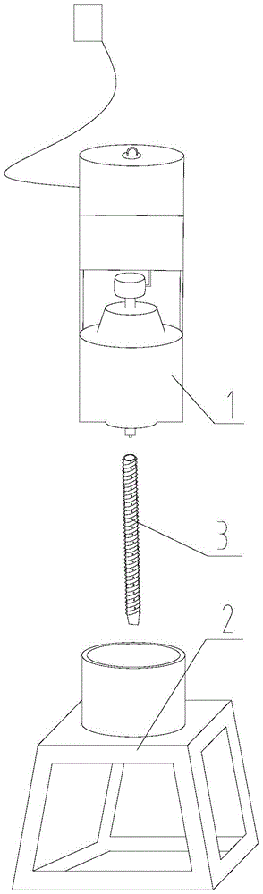
[0025] Such as figure 1 As shown, the present invention includes a machine head 1, a machine base 2 and a drill pipe part 3, the machine head 1 is installed on the machine base 2, and the lower end of the machine head 1 is connected with the drill pipe part 3.

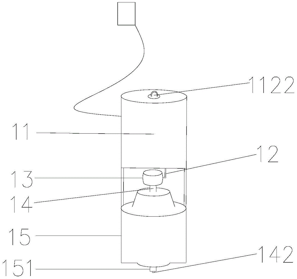
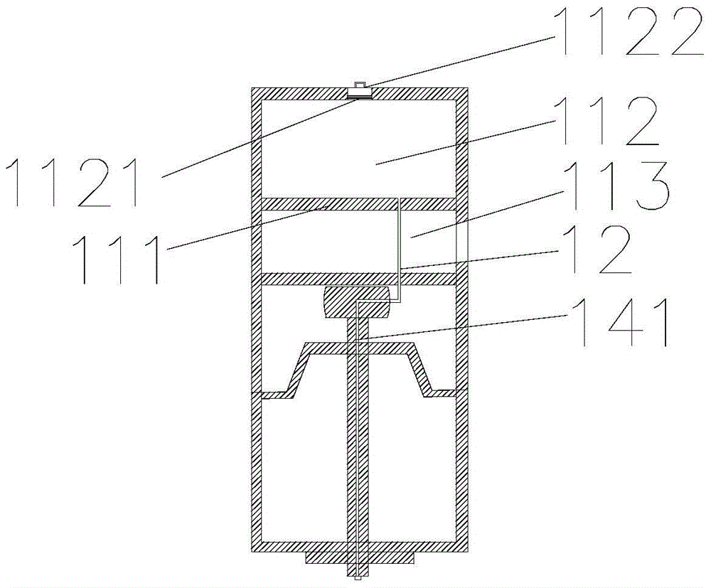
[0026] Such as figure 2 , 3 As shown, the machine head 1 includes a compression pump 11, a metal slurry pipe 12, a connector 13, a drill pipe slurry pipe 14 and a drill head 15, and the compression pump 11 includes a pump chamber, and a partition is arranged in the middle of the pump chamber 111, the pump chamber is divided into upper and lower parts, the upper part is the slurry chamber 112, the lower part is the compressor chamber 113, the compressor chamber 113 is provided with a liquid compressor, the slurry chamber 112 is connected to the connector 13 through the metal slurry pipe 12 The serous pores a...


PUM


Abstract

The invention provides a rapid grouting drilling device for a roadway base plate. The rapid grouting drilling device for the roadway base plate comprises a machine head, a machine seat and a drill rod component, wherein the machine head is installed on the machine seat, the machine head comprises a compression pump, a drill rod grout pipe and a drill machine head, an output end of the compression pump is communicated with an inner hole of the drill rod grout pipe, the drill rod grout pipe passes through the drill machine head, the drill rod component comprises a grouting rod and a drill rod, the tail end of the drill rod is connected with a drill rod connector, and the tail end of the grouting rod is connected with a grouting rod connector. The rapid grouting drilling device for the roadway base plate uses the drill rod component driven by a drill rig to drill holes, and simultaneously performs grouting, and thereby can successfully excavate into the deep of the roadway base plate so as to form holes which meet requirements by breaking a soft stratum, and is high in hole forming efficiency and large in hole forming depth.

Description

technical field [0001] The invention relates to a groutable drilling rig, in particular to a rapid grouting drilling equipment used for the roadway floor. Background technique [0002] At present, with the large deformation and instability of high-stress roadways, the cost of excavation and maintenance of many projects has doubled, which not only poses safety hazards to the working environment of workers, but also greatly hinders the normal production of mines. Generally speaking, the deformation of the roadway with high stress and weak surrounding rock is of the whole section nature, not only in the two sides and the vault of the roadway, but also the phenomenon of floor swelling. The deformation of the bottom plate has a great impact on the roadway, which not only reduces the section of the roadway, but also destroys the bottom plate foundation and track of the equipment, which greatly affects the transportation and ventilation conditions of the roadway. For the treatment...

Claims


Application Information

Patent Timeline
Patent Type & Authority Patents(China)
IPC IPC(8): E21B7/00E21B33/13
CPCE21B7/00E21B33/138
Inventor 余伟健郭罡业杜少华王卫军李树清
Owner HUNAN UNIV OF SCI & TECH
Why Eureka
Try Eureka