Eureka AIR delivers breakthrough ideas for toughest innovation challenges, trusted by R&D personnel around the world.

A variable section nozzle ring for a turbocharger

A turbocharger and nozzle ring technology, applied in the direction of machines/engines, stators, engine components, etc., can solve the problems of potential safety hazards, small contact area, easy wear of pins and shift forks, etc., and achieve high reliability, Not easy to wear and deform, high transmission reliability

Active Publication Date: 2016-02-03
PINGXIANG DEBO TECH CO LTD
View PDF8 Cites 0 Cited by
  • Summary
  • Abstract
  • Description
  • Claims
  • Application Information

AI Technical Summary

Problems solved by technology

[0002] The variable section nozzle ring assembly is a key component in today's advanced variable geometry turbochargers. For example, the Chinese patent No. 201120544236.3 discloses a variable section nozzle ring assembly. In its technical solution, the pin is fixed on On the dial, the shift fork is set on the pin, and the tail of the blade is connected with the shift fork. In this way, when the dial is rotated by external force, the pin will drive the shift fork to rotate, and the shift fork will then drive the blade to rotate to change the blade. Angle, adjust the air flow section, when the pin drives the shift fork to rotate, there will be relative sliding between the pin and the shift fork, and the line contact between the pin and the shift fork, the contact area is small, so when the relative sliding, the pin and the shift fork The shift fork is more prone to wear and tear. After the pin and the shift fork are worn out, the contact between the pin and the shift fork will be deformed, which will make the normal transmission between the pin and the shift fork impossible, so that the variable cross-section nozzle ring It cannot be used normally, which brings potential safety hazards; in addition, in its technical solution, the toggle plate is placed in the limited space formed by the installation plate and the limit pin, and the limit pin needs to be pressed by the volute of the turbocharger. Positioning, and there is a certain gap between the volute and the limit pin, when the turbocharger is working at high temperature and high speed, it is easy to cause the axial movement of the limit pin, which will cause the shifting plate to shift, which will make the The fork disengages from the dial, which prevents the nozzle ring assembly from functioning properly

Method used


Image

  • A variable section nozzle ring for a turbocharger
  • A variable section nozzle ring for a turbocharger

Examples


Embodiment Construction

[0017] The present invention will be described in further detail below in conjunction with the accompanying drawings and specific embodiments.

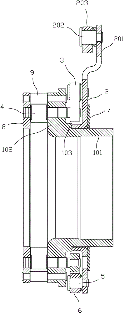
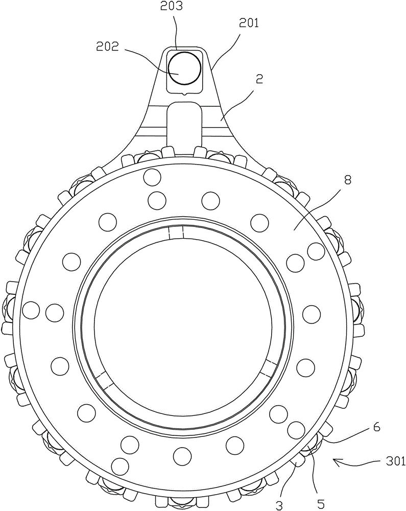
[0018] Depend on figure 1 , figure 2 As shown, the variable-section nozzle ring for a turbocharger of the present invention includes a mounting plate 1 , a dial 2 , a plurality of shift forks 3 and a plurality of pin shafts 5 connected to the dial 2 .

[0019] The mounting plate 1 includes a cylindrical portion 101 and an annular portion 102 extending radially outward from one end of the cylindrical portion 101. The cylindrical portion 101 and the annular portion 102 are formed integrally. When ringing, the cylindrical part 101 is inserted into the installation hole of the turbocharger and fixed.

[0020] The dial 2 is rotatably sleeved on the cylindrical portion 101, and a stop washer 7 for axially positioning the dial 2 is sleeved and fixed on the cylindrical portion 101, that is to say, in An annular boss 103 is arranged on the...


PUM


Abstract

The invention discloses a variable section nozzle ring for a turbocharger. The variable section nozzle ring comprises an installation disk, a shifting disk, a plurality of pin shafts and a plurality of shifting forks. The installation disk comprises a cylindrical portion and an annular portion. The annular portion extends outwards in the radial direction from one end of the cylindrical portion. The shifting disc is rotationally arranged on the cylindrical portion in a sleeving mode. The pin shafts are connected to the shifting disk. One end of each shifting fork and one corresponding blade are connected and rotate synchronously, and the other end of each shifting fork is provided with a gap. A sliding sleeve is rotationally arranged on each pin shaft in a sleeving mode. The sliding sleeves are sleeved with the shifting forks in a one-to-one corresponding mode through the gaps. The sliding sleeves can freely rotate and slide in the gaps in the shifting forks. The sliding sleeves are matched with the gaps in shape. The outer walls of the sliding sleeves are approximately square. The contact surfaces between the outer walls of the sliding sleeves and the two side walls of the gaps in the shifting forks are flat surfaces. Abrasion is reduced in the relative sliding process of the pin shafts and the shifting forks.

Description

technical field [0001] The invention relates to the technical field of turbochargers, in particular to a variable-section nozzle ring for turbochargers. Background technique [0002] The variable section nozzle ring assembly is a key component in today's advanced variable geometry turbochargers. For example, the Chinese patent No. 201120544236.3 discloses a variable section nozzle ring assembly. In its technical solution, the pin is fixed on On the dial, the shift fork is set on the pin, and the tail of the blade is connected with the shift fork. In this way, when the dial is rotated by external force, the pin will drive the shift fork to rotate, and the shift fork will then drive the blade to rotate to change the blade. Angle, adjust the air flow section, when the pin drives the shift fork to rotate, there will be relative sliding between the pin and the shift fork, and the line contact between the pin and the shift fork, the contact area is small, so when the relative slid...

Claims


Application Information

Patent Timeline
Patent Type & Authority Patents(China)
IPC IPC(8): F01D9/04F01D17/16F02B37/24
CPCY02T10/12
Inventor 吴学文黎俊韬林春兰董忠荣韩睿佳
Owner PINGXIANG DEBO TECH CO LTD
Why Eureka
Eureka Blog
Learn More