
A Method for Measuring the Tip Clearance of Concave Turbine Blades

A technology of blade tip clearance and measurement method, which is applied in the field of tip clearance measurement of turbine cavity blades and tip clearance measurement of turbine cavity blades, can solve problems such as difficulty in meeting the needs of engine development, and achieve great practical engineering application value. Good economic benefits and the effect of shortening the R&D cycle

Active Publication Date: 2017-08-25
AECC SICHUAN GAS TURBINE RES INST
View PDF3 Cites 0 Cited by
  • Summary
  • Abstract
  • Description
  • Claims
  • Application Information

AI Technical Summary

Problems solved by technology

The advanced equipment imported from abroad has carried out the measurement of the tip clearance of the fan and compressor test pieces, but the measurement of the tip clearance of the turbine blade, especially the measurement of the tip clearance of the turbine concave cavity blade which is currently in the mainstream design, is blank and difficult. Meet the development needs of the engine

Method used


Image

  • A Method for Measuring the Tip Clearance of Concave Turbine Blades
  • A Method for Measuring the Tip Clearance of Concave Turbine Blades
  • A Method for Measuring the Tip Clearance of Concave Turbine Blades

Examples


Embodiment Construction

[0029] The present invention is described in detail below in conjunction with accompanying drawing:

[0030] The measurement method provided by the invention includes signal acquisition, blade tip signal extraction and blade tip clearance calculation.

[0031] 1. Signal collection:

[0032] For the measurement of the rotating machinery signal, it is most beneficial to the signal analysis to adopt the whole cycle sampling. For tip clearance measurement, using an external synchronous trigger signal and sampling with the whole cycle sampling method can ensure that in any week of sampling data, the positional relationship between any sampling point and the blade is determined, as long as the total sampling time of a week is known The signal of each blade can be easily separated by the number of blades and the number of blades, and the calculation amount is small. The difficulty of sampling the whole cycle is how to obtain a sampling clock with a relatively high frequency. For g...


PUM


Abstract

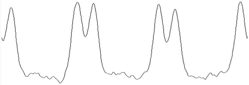
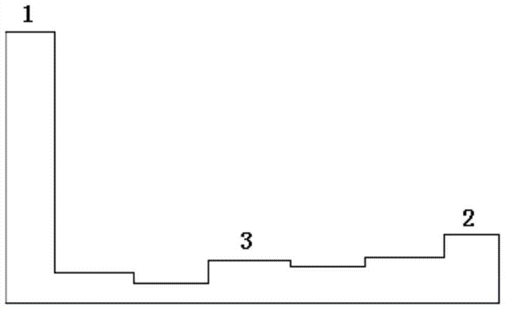
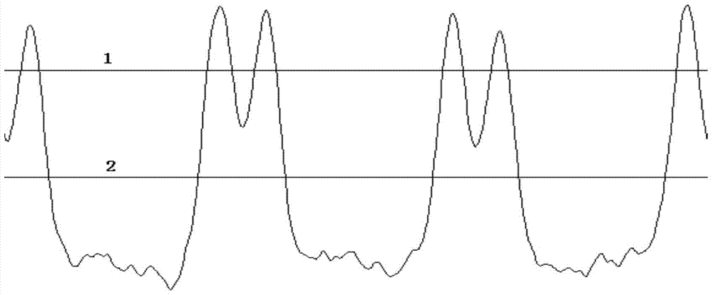
The invention belongs to a blade clearance measuring technology, and particularly relates to a method for measuring the tip clearance of turbine concave cavity blades. Disclosed by the invention is a method for measuring the tip clearance of the turbine concave cavity blades, which comprises the steps of firstly acquiring original blade tip signals and carrying out filtering and smoothing processing, then setting high and low threshold levels according to the shape of the concave cavity blades, enabling the high level to be between the peak of original blade tip clearance signals and the concave cavity valley, enabling the low level to be between inter-blade valley signals and concave cavity valley signals, differentiating different blades according to the low level, identifying two peaks according to the high level, extracting peak level, and then determining tip clearance values at a blade back side and a blade basin side according to a fitting relation between clearance and voltage. According to the invention, blade tip signals at the blade back and the blade basin of turbine concave cavity blades can be identified and extracted based on a full-period sampling technology based tip clearance measuring algorithm, variations in tip clearance at the back and the basin are monitored visually in real time, and whether collision occurs or not between the blade tip and a casing can be judged precisely.

Description

technical field [0001] The invention belongs to blade clearance measurement technology, in particular to a method for measuring the blade tip clearance of a turbine concave cavity blade, which is applied to the measurement of the blade tip clearance of a turbine concave cavity blade. Background technique [0002] Tip clearance refers to the distance between the rotor blades of the engine at all levels and the casing coating. It is a very critical parameter in engine design and has a decisive impact on the flow field structure, energy transfer, and the generation of rotating stall precursors and losses. Great impact on efficiency, fuel consumption and reliability. Studies have shown that a reduction in tip clearance of 0.0254mm can increase efficiency by 1%. This requires that the blade tip clearance be designed to be as small as possible, but it is necessary to ensure that the rotor blade tip and the casing do not collide within the full envelope of the engine, so as not to...

Claims


Application Information

Patent Timeline
Patent Type & Authority Patents(China)
IPC IPC(8): G01B21/16
CPCG01B21/16
Inventor 郭光辉韩伟李杰熊兵魏之平李杨刘先富殷光明
Owner AECC SICHUAN GAS TURBINE RES INST
Learn More