Supercharge Your Innovation With Domain-Expert AI Agents!

Pulse signal screening method and device based on principle of small-hole electrical impedance

A technology of pulse signal and screening method, applied in the field of blood cell detection, can solve the problems of complex structure, inability to ensure the accuracy of identification, influence of screening effect, etc., and achieve the effect of improving accuracy

Active Publication Date: 2015-01-21
CHENGDU SHEN MINDRAY MEDICAL ELECTRONICS TECH RES INST +1
View PDF6 Cites 10 Cited by
  • Summary
  • Abstract
  • Description
  • Claims
  • Application Information

AI Technical Summary

Problems solved by technology

The disadvantage of this method is that the realization structure is complicated and the cost is high
[0005] The second is to try to identify the pulse signal amplitude that can effectively express the cell volume through complex processing of each pulse signal, but this method has limited improvement on abnormal signals, and has no substantial improvement effect on some abnormal signals with severe distortion
However, there are many factors that affect the identification results of pulse signal full width or half width in the existing technology, such as the size, shape, and interference noise of the pulse signal, etc., which will affect the full width or half width of the pulse signal, resulting in the inability to ensure Accurate identification, the screening effect will naturally be affected
And the existing method of screening normal signals through the full width or half width of the pulse signal can eliminate the interference of abnormal signals to the detection results to a certain extent, but the size, shape, and interference noise of the pulse signal will affect the full width of the pulse signal. Width or half-width constitute an influence, so the current screening method is still not accurate enough

Method used


Image

  • Pulse signal screening method and device based on principle of small-hole electrical impedance
  • Pulse signal screening method and device based on principle of small-hole electrical impedance
  • Pulse signal screening method and device based on principle of small-hole electrical impedance

Examples


Embodiment Construction

[0045] The pulse signal screening method and device based on the small hole impedance principle provided by the present invention can be applied to the small hole impedance method. By detecting and calculating the edge width of the pulse signal, the method and device can more accurately identify normal signals and abnormal signals, so as to effectively improve the accuracy of detecting blood cell volume distribution parameters by the small hole impedance method.

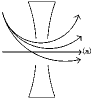
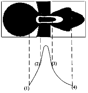
[0046]As known to those skilled in the art, in the process of detecting the volume of blood cells by the small hole impedance method, when the cells enter the electric field area around the small hole sensor, they will start to generate electrical pulse signals, such as image 3 (1) position in . When the cell passes through the small hole and completely moves out of the electric field area, the electric pulse signal tends to end, such as image 3 (4) in the position. Generally, the width between (1)-(4) is regarde...


PUM


Abstract

The invention provides a pulse signal screening method and a device based on the principle of small-hole electrical impedance. The method includes: acquiring pulse signal generated when each cell passes through a small-hole sensor; calculating the edge width of the pulse signal; determining whether the edge width of the pulse signal is within a normal signal edge width range; determining that the pulse signal is normal if the edge width of the pulse signal is within the normal signal edge width range; and determining that the pulse signal is abnormal if the edge width of the pulse signal is not within the normal signal edge width range, wherein the edge width is a time interval between a point having the maximum pulse signal rising edge slope and a point having the minimum pulse signal falling edge slope. By detection and calculation of the edge width of the pulse signal, the method and the device can recognize normal and abnormal signal more accurately, thus effectively improving the accuracy of a small-hole electrical impedance method for detecting blood cell volume distribution parameters.

Description

technical field [0001] The invention relates to the field of blood cell detection, in particular to a pulse signal screening method and device based on the principle of small hole impedance. Background technique [0002] The small hole impedance principle is a classic detection principle of blood cell analyzers. This principle is to detect the volume of cells by identifying the amplitude of the electrical pulse signal generated when cells pass through small holes. Due to the characteristics of the electric field and flow field distribution inside and outside the small hole, only a single cell passes through the axial center of the small hole in a straight line (such as figure 1 The pulse signal generated by the path (a) in (a)), the signal amplitude can express the cell volume well, and this kind of signal is called "normal signal" in this paper, such as figure 2 (a) Pulse signal in (a). while individual cells pass through other pathways (such as figure 1 The pulse signa...

Claims


Application Information

Patent Timeline
IPC IPC(8): G01N15/10
Inventor 仝文俊史兴阮雷
Owner CHENGDU SHEN MINDRAY MEDICAL ELECTRONICS TECH RES INST
Features
  • R&D
  • Intellectual Property
  • Life Sciences
  • Materials
  • Tech Scout
  • Unparalleled Data Quality
  • Higher Quality Content
  • 60% Fewer Hallucinations
Learn More