Liquid crystal display panel, discharging method thereof and display device

A liquid crystal display panel and discharge terminal technology, applied in static indicators, instruments, nonlinear optics, etc., can solve the problems that the positive and negative charges cannot be completely offset, and the liquid crystal orientation cannot be restored, so as to avoid afterimages and afterimages, ensure quality, Avoid afterimage effects

Inactive Publication Date: 2015-01-21
BOE TECH GRP CO LTD +1
View PDF8 Cites 41 Cited by
  • Summary
  • Abstract
  • Description
  • Claims
  • Application Information

AI Technical Summary

Problems solved by technology

During the polarity reversal process of the electric field, the positive and negative charges on the two plates of the liquid crystal capacitor cannot be completely offset due to the leakage of the TFT and the crosstalk of the parasitic capacitance on the liquid crystal capacitor, resulting in a certain plate of the liquid crystal capacitor The generation of DC residual charge (that is, DC residual charge), the accumulation of this part of the residual charge will make the liquid crystal orientation unable to return to the initial state, forming afterimages

Method used


Image

  • Liquid crystal display panel, discharging method thereof and display device
  • Liquid crystal display panel, discharging method thereof and display device

Examples


Embodiment 1

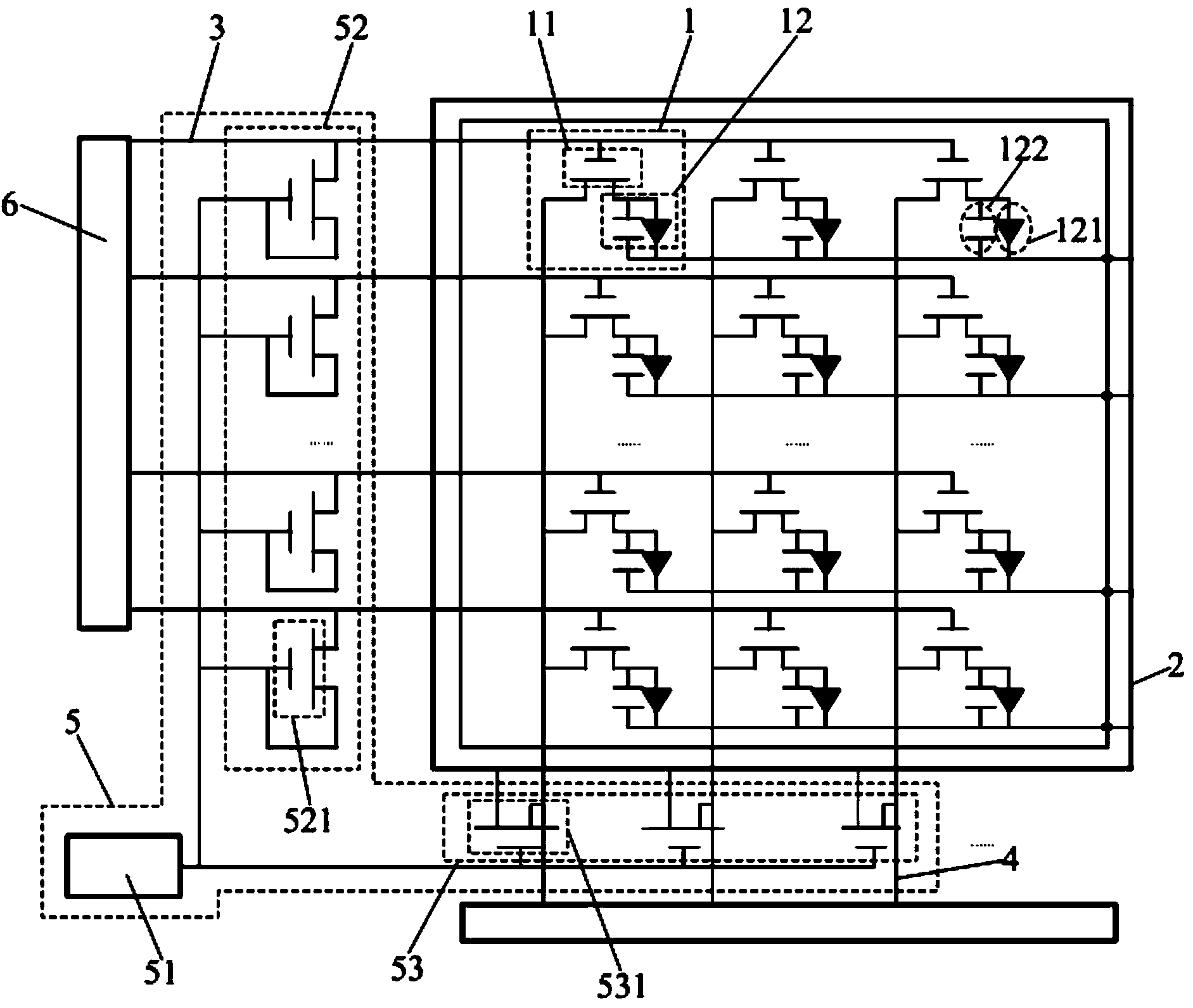
[0028] This embodiment provides a liquid crystal display panel, such as figure 1 As shown, it includes a plurality of pixel structures 1 arranged in a matrix, discharge terminals 2, a plurality of scanning lines 3 and data lines 4, each pixel structure 1 includes a switch unit 11 and a pixel unit 12 connected to each other, and the switch unit 11 is used for To turn on and off the pixel unit 12, it also includes a discharge circuit 5, the discharge circuit 5 is respectively connected to the scan line 3, the data line 4 and the discharge terminal 2, and is used to make the scan line 3 discharge and scan, and turn on the switch unit 11, so that The remaining charge on the pixel unit 12 is discharged to the discharge terminal 2 through the data line 4 .

[0029] In this embodiment, multiple scan lines 3 are connected to multiple rows of switch units 11 in one-to-one correspondence, and multiple data lines 4 are connected to multiple columns of switch units 11 in one-to-one corres...

Embodiment 2

[0048] This embodiment provides a display device, including the liquid crystal display panel in Embodiment 1.

[0049] By using the liquid crystal display panel in Example 1, the residual charge in the display device can be completely released, so that the display device can avoid afterimages and afterimages during startup, shutdown and display, thereby ensuring that the display device display quality.

[0050] The display device provided by the present invention may be a liquid crystal display device of any mode such as TN, ADS, IPS, LTPS and the like. The display device can be any product or component with a display function, such as a liquid crystal panel, a liquid crystal TV, a monitor, a mobile phone, a navigator, and the like.


PUM


Abstract

The invention provides a liquid crystal display panel, a discharging method thereof and a display device. The liquid crystal display panel comprises a plurality of pixel structures arranged in a matrix mode, discharging ends, a plurality of scanning lines and data lines. Each pixel structure comprises a switch unit and a pixel unit connected with each other, and each switch unit is used for starting and stopping the corresponding pixel unit. The liquid crystal display panel further comprises a discharging circuit connected with the scanning lines, the data lines and the discharging ends and is used for enabling the scanning lines to conduct discharging scanning and starting the switch units, so that residual charges on the pixel units are discharged to the discharging ends through the data lines. According to the liquid crystal display panel, the discharging circuit is arranged, the residual charges on the pixel units are discharged more thoroughly, and appearance of residual images in the display process of the liquid crystal display panel or after display of the liquid crystal display panel is finished is further avoided.

Description

technical field [0001] The present invention relates to the field of display technology, in particular to a liquid crystal display panel, a discharge method thereof, and a display device. Background technique [0002] In recent years, liquid crystal displays have become popular and become mainstream display devices in the market due to their advantages such as low operating voltage, low power consumption, low radiation, small space occupation, and thin, light and beautiful appearance. At present, people's requirements for liquid crystal displays are constantly increasing, especially for the display quality of the entire display. Among them, the afterimage problem is one of the most critical factors affecting the display quality of the picture. [0003] A traditional liquid crystal display panel is composed of two transparent substrates sandwiching a liquid crystal layer. A plurality of data lines and a plurality of scanning lines are formed on one substrate, and a pixel st...

Claims


Application Information

Patent Timeline
Patent Type & Authority Applications(China)
IPC IPC(8): G02F1/133G02F1/1362
CPCG02F1/13306G02F1/136204
Inventor 贺伟李兴华朴承翊
Owner BOE TECH GRP CO LTD
Why Eureka
Try Eureka