Method for monitoring mountain landslide and debris flow in mountainous areas based on unmanned aerial vehicle

A landslide and unmanned aerial vehicle technology, applied in the direction of instruments, alarms, etc., can solve the problems of consuming a lot of time, wasting rescue time and energy, and inconvenient transportation, and achieve the effect of safe operation, low use cost, and improved rescue efficiency

Active Publication Date: 2015-01-21
恒创数字科技(江苏)有限公司
View PDF6 Cites 37 Cited by
  • Summary
  • Abstract
  • Description
  • Claims
  • Application Information

AI Technical Summary

Problems solved by technology

[0004] Due to the complex road conditions in mountainous areas, when natural disasters such as landslides and mudslides occur in mountainous areas, the failure of rescuers to rush to the accident site in time is one of the main reasons for casualties in the area where the accident occurred; because the natural disaster itself is the structure of the mountain Due to the complex road conditions, it is impossible to manually determine and judge the specific location of rescuers

Method used


Image

  • Method for monitoring mountain landslide and debris flow in mountainous areas based on unmanned aerial vehicle

Examples


Embodiment 1

[0024] Example 1: A method for monitoring landslides and debris flows in mountainous areas based on unmanned aerial vehicles, comprising the following steps:

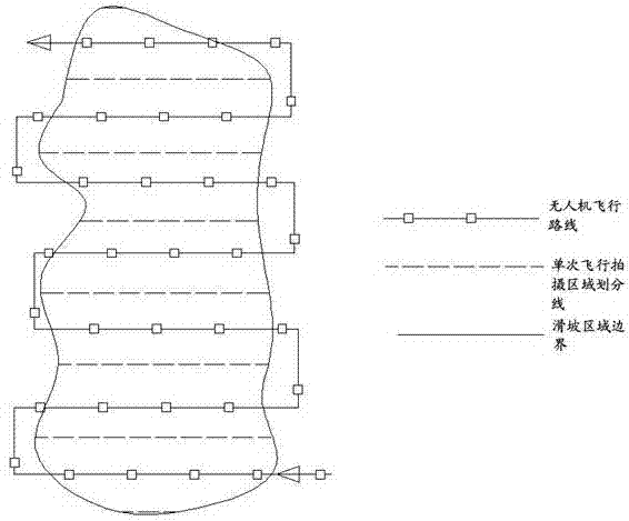
[0025] a) When a landslide or mudslide accident occurs in a mountainous area, use known information and computer technology to draw the accident area and flight route for the first flight of the UAV;

[0026] b) According to the initial flight route formulated by the computer, the UAV performs its first flight. During the flight, the UAV is equipped with imaging equipment. When it enters the estimated accident area, the imaging equipment is turned on, and the whole process of the UAV is taken with the positioning equipment. On-site mountain conditions in the flight area;

[0027] c) According to the video recorded during the first flight and the coordinates recorded by the positioning equipment, the images and data obtained by the aerial photography of the drone are imported into the 3D simulation computer for manual ...

Embodiment 2

[0033] Example 2: During the initial flight of the UAV in step b), the UAV flies along the sideline of the planned accident area to confirm the specific scope of the accident area; if it is found in step c) that the actual area of ​​the accident area is larger than the planned accident area area, step a) needs to be re-executed;

Embodiment 3

[0034] Example 3: Step f) In the actual process of manual comparison, when manual observation and comparison are found, when rescuers or disaster victims are found, cooperate with the positioning equipment carried by the drone to determine the location information of the personnel, and re-execute d)-f) Step, in the process of repeating the flight, it is necessary to send rescue to the designated location for rescue.


PUM


Abstract

The invention discloses a method for monitoring mountain landslide and debris flow in mountainous areas based on an unmanned aerial vehicle. The method is characterized in that photographing is carried out through directional cruising of the unmanned aerial vehicle and an imaging device and a positioning device which are carried by the unmanned aerial vehicle, and collected data is analyzed through computer software so as to work out an accurate rescue mode and a path method in allusion to mountain landslide and debris flow in the mountainous areas. The method disclosed by the invention can accurately judge the damage area of a region in which mountain landslide or debris flow occurs through applying unmanned aerial vehicle remote sensing technologies to the field of mountainous area sudden accident rescue, and seamless searching is carried out by means of the unmanned aerial vehicle through computer modeling and planning, thereby monitoring damage conditions of the affected region quickly and comprehensively, transmitting information to a rescue command center timely, being convenient for rescue workers to plan an accurate rescue path timely, and greatly improving the rescue efficiency; and the method is applicable to detection work for affected mountainous areas under various complex conditions.

Description

technical field [0001] The invention relates to the field of emergency rescue in mountainous areas, in particular to a method for monitoring landslides and debris flows in mountainous areas based on an unmanned aerial vehicle. Background technique [0002] Landslides and mudslides refer to special natural disasters caused by torrential rain, snowstorm or other natural disasters in mountainous areas or other areas with deep valleys and steep terrain, which carry a large amount of sediment and stones. Landslides and debris flows have the characteristics of suddenness, fast flow, large flow, large material capacity and strong destructive power. Traffic facilities such as roads and railways and even villages and towns are often washed away, causing huge losses. [0003] UAV remote sensing systems mostly use small digital cameras (or scanners) as airborne remote sensing equipment. Compared with traditional aerial photographs, there are problems such as small image size and large...

Claims


Application Information

Patent Timeline
IPC IPC(8): G08B21/10
CPCG08B21/10
Inventor 汤洁泉王苏宁沙敏赵雪凤李亮
Owner 恒创数字科技(江苏)有限公司
Why Eureka
Try Eureka