Distributed radio monitoring network and method

A technology for radio monitoring and monitoring network, applied in wireless communication, electrical components, transmission systems, etc., to achieve the effect of reducing costs, realizing information sharing, and reducing the possibility of reflection

Inactive Publication Date: 2015-01-21
THE 41ST INST OF CHINA ELECTRONICS TECH GRP
View PDF4 Cites 2 Cited by
  • Summary
  • Abstract
  • Description
  • Claims
  • Application Information

AI Technical Summary

Problems solved by technology

[0005] The purpose of the present invention is to provide a distributed radio monit...

Method used


Image

  • Distributed radio monitoring network and method
  • Distributed radio monitoring network and method
  • Distributed radio monitoring network and method

Examples


Embodiment Construction

[0025] The specific embodiment of the present invention will be further described below in conjunction with accompanying drawing and specific embodiment:

[0026] Introduction of proper nouns:

[0027] TCP / IP: Transmission Control Protocol / Internet Protocol, UDP: User Datagram Protocol.

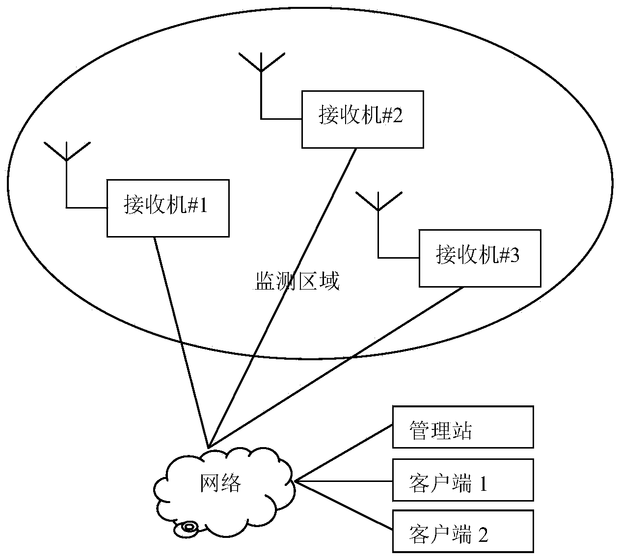
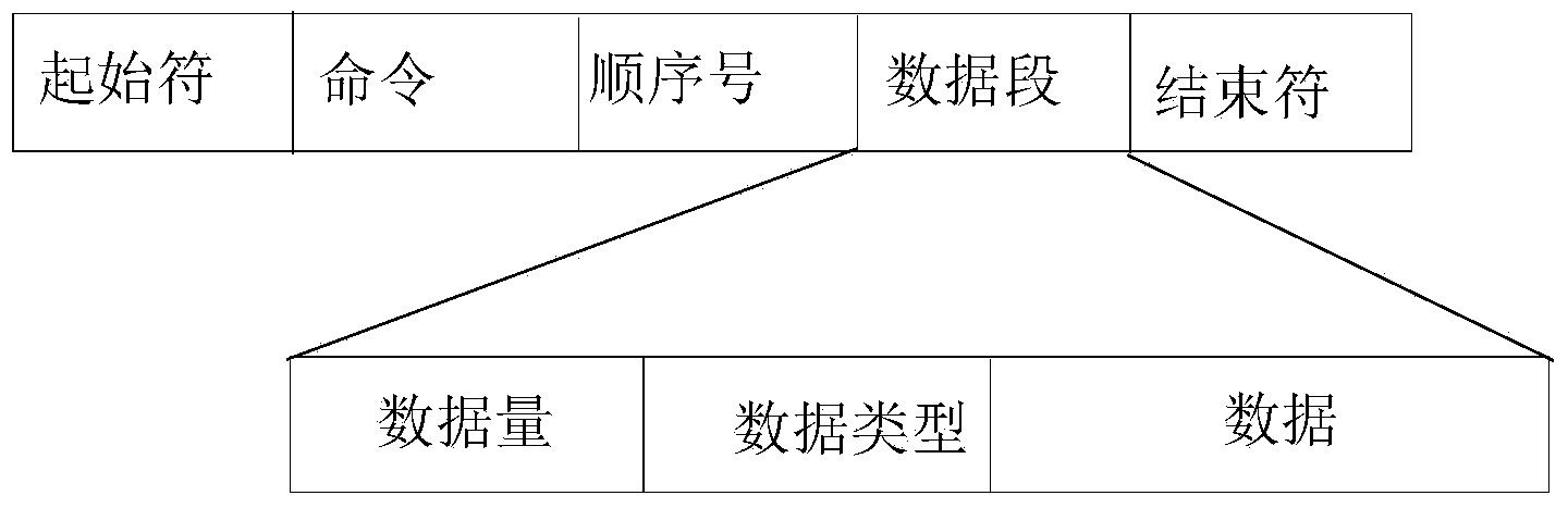
[0028] Such as figure 1 As shown, a distributed radio monitoring network is composed of a cluster of miniaturized receiver modules, a management station, a client, and network interconnection equipment. The monitoring network realizes communication based on the TCP / IP protocol suite, and the client and The receiver uses the TCP protocol to transmit instructions and data, and the management station uses the UDP protocol and multicast to search for the receiver. All instructions are used as figure 2 The frame format shown. Among them, the start symbol is the 4-byte ASCII code of "EI41", representing the beginning of the frame; the command segment is the 16-byte ASCII code, representing diff...


PUM


Abstract

The invention relates to a distributed radio monitoring network. The distributed radio monitoring network comprises a miniaturization receiver module cluster, a management station, a client terminal and a network connecting device; the miniaturization receiver module cluster is used for signal perception, the management station is used for network management, and the client terminal is used for executing monitoring tasks. The monitoring network is based on a TCP/IP protocol family to achieve communication, the client terminal and receivers transmit commands and data according to a TCP protocol, and the management station searches for the receivers according to a UDP protocol and multicast. The distributed monitoring network is adopted, the receivers can be closer to a signal transmission source in geographic position, and therefore the signal transmission possibility before signals are received is decreased; a monitoring device does not need high performance any more, and cost is reduced.

Description

technical field [0001] The invention belongs to the field of radio monitoring, in particular to a distributed radio monitoring network and a monitoring method. Background technique [0002] In order to ensure that the electromagnetic environment of wireless communication is free from interference and damage, it is necessary to monitor the radio signals propagating in space. Generally speaking, a monitoring site is a monitoring system consisting of receiving antennas, receivers, industrial computers and monitoring software. It uses fixed local oscillators or frequency sweeps to continuously observe electromagnetic signals in specific frequency bands. Once illegal and interference signals are found , that is, use a direction-finding system composed of a direction-finding antenna and a direction-finding instrument to find the direction and position of the signal, and find out the illegal station or source of emission. [0003] At present, the monitoring mode of fixed station a...

Claims


Application Information

Patent Timeline
IPC IPC(8): H04W24/00H04L29/08
CPCH04W24/00H04L63/30H04L67/10H04L67/01
Inventor 杨青黄丙志裴广超牛大胜
Owner THE 41ST INST OF CHINA ELECTRONICS TECH GRP
Why Eureka
Try Eureka