FPGA (Field Programmable Gate Array) based lower limb rehabilitation equipment
A technology for rehabilitation equipment and lower limbs, which is applied in the field of medical devices and can solve the problem of not being able to collect index data of paralyzed patients.
- Summary
- Abstract
- Description
- Claims
- Application Information
AI Technical Summary
Problems solved by technology
Method used
Image

Examples
Embodiment Construction
[0009] Specific embodiments of the present invention will be described below in conjunction with the accompanying drawings.
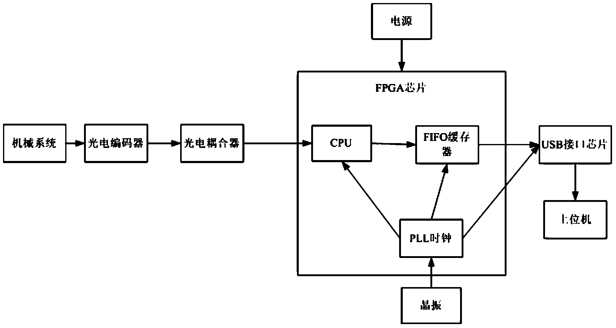
[0010] see figure 1 , the FPGA-based lower limb rehabilitation device in the embodiment of the present invention includes a mechanical system, a photoelectric encoder, a photocoupler, an FPGA chip, a USB interface chip, a PC host computer, a power supply, and a crystal oscillator.
[0011] The photoelectric encoder is installed on the mechanical system, which can collect the displacement data of the lower limbs, and transmit the data to the photocoupler through the input port of the photocoupler.
[0012] The photoelectric coupler is used to reduce the digital signal voltage output by the photoelectric encoder, so that the voltage matches the FPGA chip.
[0013] The FPGA chip is connected with the output port of the optocoupler. The FPGA chip selected in this embodiment is a Cyclone III EP3C series device of Altera Company, and its model is EP3C16Q240...
PUM
 Abstract
Description
Claims
Application Information
PatSnap Eureka turns technology decisions into work you can execute. Powered by our Innovation Knowledge Graph, it runs expert workflows across engineering, life sciences, materials and intellectual property. Get your review-ready output in minutes.


