
Environmental protection and constant temperature vacuum double layer fire pot

A constant temperature and vacuum technology, used in other medical devices, heating appliances for treatment, cooling appliances for treatment, etc., can solve the problems of no cupping heat, inconvenient cupping methods, etc., and achieve the effect of restoring function well.

Inactive Publication Date: 2015-01-28
柴雪青
View PDF10 Cites 1 Cited by
  • Summary
  • Abstract
  • Description
  • Claims
  • Application Information

AI Technical Summary

Problems solved by technology

However, the tank body of the vacuum cupping device is cold, and it loses the characteristics of the temperature of the cupping tank. It does not have the heat of the previous cupping tank. The vacuum cupping device solves the inconvenience of cupping and at the same time loses an advantage that is "heat".

Method used


Image

  • Environmental protection and constant temperature vacuum double layer fire pot
  • Environmental protection and constant temperature vacuum double layer fire pot

Examples


example 1

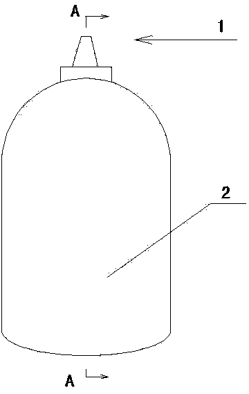
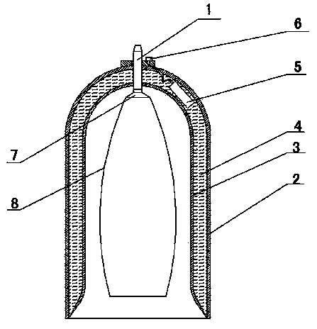
[0021] see Figure 1~2 , a cavity is formed in the tank wall of the vacuumized tank body, so that the tank wall is divided into an inner wall 3 and an outer wall 2, a heat conductor 4 is arranged in the cavity, and a heating device 5 is installed in the heat conductor body; the heating device passes through a wire and a power supply The socket 6 is connected together, and the power socket is connected with a 5~12V DC power supply.

[0022] An annular magnetic block 7 is arranged at the air suction port of the vacuumized tank body.

[0023] A conical net pocket 8 is provided at the air suction port of the vacuumized tank body.

[0024] The heat conductor is heat conduction oil.

[0025] The heating device is a constant temperature heater with a temperature sensor.

[0026] Its use method is as follows: connect 5V DC power supply or 12V DC power supply, preheat the present invention, when the predetermined temperature is reached, use a vacuum cupping device to perform body cu...

Embodiment 2

[0030] see Figure 1~2 , a cavity is formed in the tank wall of the vacuumized tank body, so that the tank wall is divided into an inner wall 3 and an outer wall 2, a heat conductor 4 is arranged in the cavity, and a heating device 5 is installed in the heat conductor body; the heating device passes through a wire and a power supply The sockets 6 are connected together, and the power socket is connected to the 220V AC power supply.

[0031] An annular magnetic block 7 is arranged at the air suction port of the vacuumized tank body.

[0032] A conical net pocket 8 is provided at the air suction port of the vacuumized tank body.

[0033] The heat conductor is heat conduction oil.

[0034] The heating device is a PTC heating module with a temperature sensor.

[0035] The method of use is as follows: switch on the 220V AC power supply, preheat the present invention, and when the predetermined temperature is reached, use a vacuum cupping device to perform body cupping, the perso...


PUM


Abstract

The invention provides an environmental protection and constant temperature vacuum double layer fire pot. The environmental protection and constant temperature vacuum double layer fire pot aims as solving the problem that a pot body of an existing vacuum pumping fire pot is cool and needs to be heated by using external conditions when the existing vacuum pumping fire pot is used. The technical essential includes that a cavity is formed in the pipe wall of a vacuum pumping pot body of the environmental protection and constant temperature vacuum double layer fire pot, a heat conduction body is arranged in the cavity, a heating device is installed in the heat conduction body, and the heating device is connected together with a power source socket through a lead wire. The environmental protection and constant temperature vacuum double layer fire pot achieves cupping by using a vacuum pumping device, generates tepid stimulation on partial skin through negative pressure in the pot body, heat of the pot body and properties of traditional Chinese medicine, which are emitted and enter a human body, and can enable an organism to recover functions well.

Description

technical field [0001] The invention belongs to the technical field of traditional Chinese medicine physiotherapy equipment, and mainly relates to an environment-friendly constant temperature vacuum double-layer cupping jar. Background technique [0002] Cupping, in ancient times, is to use fire to burn out the oxygen in the container, so that the container generates negative pressure and maintains a certain temperature, so it is called cupping. [0003] Cupping method is also known as "cupping gas", and it was called "horn method" in ancient times. Its principle is a kind of treatment that uses cups and jars as tools, and uses heat to remove the air in it to generate negative pressure, so that it can be absorbed on the skin and cause congestion. Ancient doctors used it to suck blood and drain pus when treating sores and abscesses, and later expanded its application to internal diseases such as tuberculosis and rheumatism. After the founding of the People's Republic of Chi...

Claims


Application Information

Patent Timeline
Patent Type & Authority Applications(China)
IPC IPC(8): A61M1/00A61F7/00A61M37/00
CPCA61M1/0003A61F7/00A61F2007/0001A61M37/00A61M2037/0007A61M2202/0021A61M2205/05A61M2205/073A61M2210/04
Inventor 柴佳良柴雪青
Owner 柴雪青
Learn More