Photocatalyst dip coater

A technology of dip coating machine and photocatalyst, which is applied in the direction of coating, liquid coating device on the surface, surface pretreatment, etc. It can solve the problems of continuous production of mechanical devices, inability to coil into rolls, low production efficiency, etc., and achieve production Efficiency improvement, low cost and low labor intensity

Inactive Publication Date: 2015-01-28
天津发洋环保科技有限公司
View PDF5 Cites 0 Cited by
  • Summary
  • Abstract
  • Description
  • Claims
  • Application Information

AI Technical Summary

Problems solved by technology

[0002] The photocatalyst net obtained by loading the nano photocatalyst material on the metal net is the core purification component of some photocatalyst air purification devices. The preparation of the photocatalyst net is usually sprayed or dipped. The material is hard and cannot be coiled into rolls. Regardless of the spraying or dipping process, continuous production with mechanical devices is not possible. Up to now, manual work is still used, which has the disadvantages of high labor intensity and low production efficiency.
So far there is no professional dip coating device suitable for photocatalyst dip coating of iron metal mesh

Method used


Image

  • Photocatalyst dip coater

Examples


Embodiment Construction

[0017] In order to make the technical problems, technical solutions and beneficial effects solved by the present invention clearer, the present invention will be further described below in conjunction with the accompanying drawings and embodiments. It should be understood that the embodiments described here are only used to explain the present invention, not to limit the present invention.

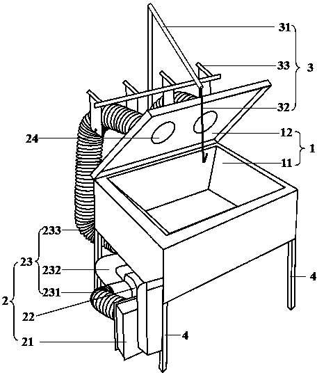
[0018] Such as figure 1 As shown, a photocatalyst dip coating machine is composed of a dip coating chamber (1), a hot air drying device (2), a lifting frame (3) and a support (4). The structure of the dip coating chamber (1) includes a cone Shaped bottom tank (11) and square upper cover (12), the structure of the hot air drying device (2) includes a heater (21), a fan (22) and an air supply pipe (23), the dipping chamber ( The conical bottom tank (11) of 1) is fixed on the bracket (4), and the square upper cover of the dipping chamber (1) is connected with the air supply pipe (23) of the ...


PUM


Abstract

The invention provides a photocatalyst dip coater. The photocatalyst dip coater consists of a dip coating chamber, a hot air drying device, a lifting rack and a support; the dip coating chamber structurally comprises a cone-shaped bottom groove and a square upper cover; the hot air drying device structurally comprises a heater, a draught fan and a blast pipe; the lifting rack structurally comprises a lifting rod and a suspension hook; the cone-shaped bottom groove of the dip coating chamber is fixed on the support; the square upper cover of the dip coating chamber is connected with the blast pipe of the hot air drying device; air outlets are formed in the square upper cover; the lifting rack is arranged at the back of the dip coating chamber, and is fixed on the support. The photocatalyst dip coater is reasonable and compact in design, simple in working procedure, low in labor intensity and high in production efficiency, and can be applied to photocatalyst dip coating operation of iron metal nets.

Description

technical field [0001] The invention belongs to the field of dip coating devices for nanometer materials, and relates to a photocatalyst dip coating machine. Background technique [0002] The photocatalyst net obtained by loading the nano photocatalyst material on the metal net is the core purification component of some photocatalyst air purification devices. The preparation of the photocatalyst net is usually sprayed or dipped. The material is relatively hard and cannot be rolled into rolls. Whether it is spraying or dipping, it cannot be continuously produced by mechanical devices. Up to now, manual operations are still used, which has the disadvantages of high labor intensity and low production efficiency. So far, there is no professional dip-coating device suitable for photocatalyst dip-coating of ferrous metal mesh. Contents of the invention [0003] The purpose of the present invention is to overcome the defect of prior art, provide a kind of photocatalyst dip-coati...

Claims


Application Information

Patent Timeline
Patent Type & Authority Applications(China)
IPC IPC(8): B05C3/10B05C13/02B05D1/18B05D3/02B05D3/04
CPCB05C3/10B05C13/02B05D1/18B05D3/0218B05D3/0254B05D3/0453
Inventor 杨立新
Owner 天津发洋环保科技有限公司
Why Eureka
Try Eureka