
Curved steel plate forming method and curved steel plate forming equipment

A technology for forming equipment and steel plates, applied in metal processing equipment, forming tools, feeding devices, etc., can solve the problems of harsh working environment, prolonging production time, and high labor intensity, so as to reduce the dependence of workers on experience and improve production efficiency , the effect of reducing labor intensity

Active Publication Date: 2015-01-28
SHENZHEN INST OF ADVANCED TECH
View PDF10 Cites 8 Cited by
  • Summary
  • Abstract
  • Description
  • Claims
  • Application Information

AI Technical Summary

Problems solved by technology

This empirical manual processing mode inevitably has shortcomings: First, the acquisition of experience requires long-term accumulation, and it is difficult for ordinary workers to master this technology in a short period of time; it is not easy to train technicians for water and fire bending processing workers, and their levels are also uneven. together
Secondly, because the water and fire bending workers are directly exposed to flames and water vapor, the working environment is harsh and the labor intensity is high. Most young workers are unwilling to engage in this type of work. As the old workers gradually retire, experienced processing workers are increasingly scarce. There is a danger of faults in this process
At the same time, workers in water and fire bending work have long-term direct contact with flames and water vapor, and the working environment is harsh and labor-intensive
In addition, the one-time forming rate of the steel plate is low, and it is necessary to manually inspect the forming quality of the sample plate, and continuously carry out secondary or multiple processing to correct the shape of the steel plate, which not only prolongs the production time, but also inevitably has high fluctuations in the processing quality of the steel plate. Big problem, difficult to achieve precision control

Method used


Image

  • Curved steel plate forming method and curved steel plate forming equipment
  • Curved steel plate forming method and curved steel plate forming equipment
  • Curved steel plate forming method and curved steel plate forming equipment

Examples


Embodiment Construction

[0029] In order to make the object, technical solution and advantages of the present invention clearer, the present invention will be further described in detail below in conjunction with the accompanying drawings and embodiments. It should be understood that the specific embodiments described here are only used to explain the present invention, not to limit the present invention.

[0030] It should be noted that when an element is referred to as being “fixed on” or “disposed on” another element, it may be directly on the other element or there may be an intervening element at the same time. When an element is referred to as being "connected to" another element, it can be directly connected to the other element or intervening elements may also be present.

[0031] It should also be noted that the orientation terms such as left, right, up, and down in this embodiment are only relative concepts or refer to the normal use state of the product, and should not be regarded as limiti...


PUM


Abstract

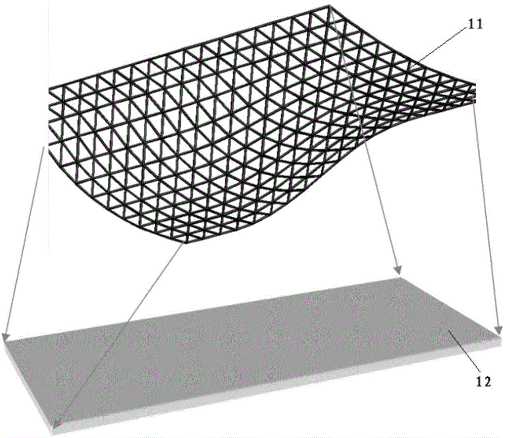
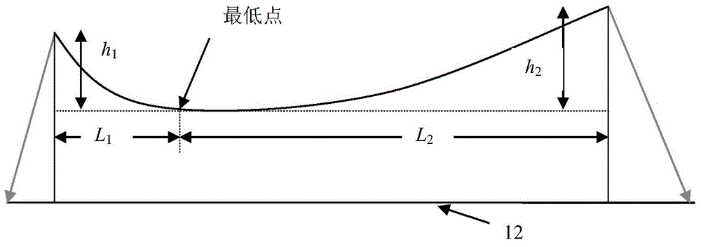
The invention is suitable for the technical field of curved steel plate production and discloses a curved steel plate forming method and curved steel plate forming equipment. The curved steel plate forming method comprises the following steps: designing a three-dimensional model of a curved steel plate as well as the initial shape and size of the steel plate unfolded to be in a planar state, arranging a supporting adsorption platform part on one side of the steel plate, arranging a punching head on the other side of the steel plate, determining the position and downward pressing quantity of the punching head according to the section profile shape of the steel plate, and pressing the steel plate downwards. The curved steel plate forming method is adopted in the curved steel plate forming equipment. According to the curved steel plate forming method and the curved steel plate forming equipment which are provided by the invention, the complicated curved steel plate such as the complicated curved surface of a ship body can be progressively formed, the flow process is simplified, the forming process is automated, the production efficiency is greatly improved, the dependence on the experience of workers is effectively reduced, the production process is free from dust and smog, waste gas and waste water cannot be generated, the environment is protected, and the labor intensity of the workers is greatly reduced.

Description

technical field [0001] The invention belongs to the technical field of curved steel plate production, and in particular relates to a curved steel plate forming method and curved steel plate forming equipment which can be used for preparing multi-curvature bent plates. Background technique [0002] The shipbuilding industry is a strategic industry that provides technical equipment for water transportation, marine development and national defense construction, and is an important part of the advanced equipment manufacturing industry. The status of the shipbuilding industry in the national economy is very significant, and it is known as the "crown of comprehensive industries". A big ship is like a small town. According to statistics, among the 116 industrial sectors of the national economy, the shipbuilding industry is directly related to 97 of them, accounting for 84% of the related areas. In 2013, the national shipbuilding completion volume was 45.34 million deadweight tons ...

Claims


Application Information

Patent Timeline
Patent Type & Authority Applications(China)
IPC IPC(8): B21D22/02B21D43/00
CPCB21D11/00B21D31/005B21D37/00B21D43/003
Inventor 何凯李赳华左启阳党晓兵王澎涛魏树国杜如虚
Owner SHENZHEN INST OF ADVANCED TECH
Learn More