Equipment for enabling copper pipe to pass through fin of condenser

A condenser and copper tube technology, which is applied in the field of air-conditioning condenser processing equipment, can solve problems such as low production efficiency and safety, inability to realize mass production, and difficulty in passing copper tubes in sequence, so as to reduce labor costs and equipment loss, overcome cumbersome and unsafe factors, and improve the effect of equipment stability

Active Publication Date: 2015-01-28
广州绅特模具制造有限公司
View PDF7 Cites 19 Cited by
  • Summary
  • Abstract
  • Description
  • Claims
  • Application Information

AI Technical Summary

Problems solved by technology

When the size of the copper pipe is short, it is easy to cause work-related accidents caused by the mold pinching the hand. When the manipulator is used to grab and place the copper pipe, due to the poor rigidity of the copper pipe, it is easy to cause deformation of the copper pipe and damage to the equipment due to improper force applied by the manipulator. scrapping
Since the fin is a sheet structure made of aluminum foil with a thickness of about 0.1mm, its material is very soft, and the thickness of the tube wall of the copper tube is only about 0.3mm, when the U-shaped copper tube passes through the stacked fins It is difficult to ensure that the copper tubes can pass through all the fins in sequence, and due to the different magnitudes of artificial force, the shaking and offset of the copper tubes cannot be avoided, resulting in deformation of the fin holes and copper tubes
The entire equipment manufacturing process takes a long time, the production efficiency and safety are low, and mass production cannot be realized

Method used


Image

  • Equipment for enabling copper pipe to pass through fin of condenser
  • Equipment for enabling copper pipe to pass through fin of condenser
  • Equipment for enabling copper pipe to pass through fin of condenser

Examples


Embodiment Construction

[0053] The specific embodiment of the present invention will be further described below in conjunction with accompanying drawing:

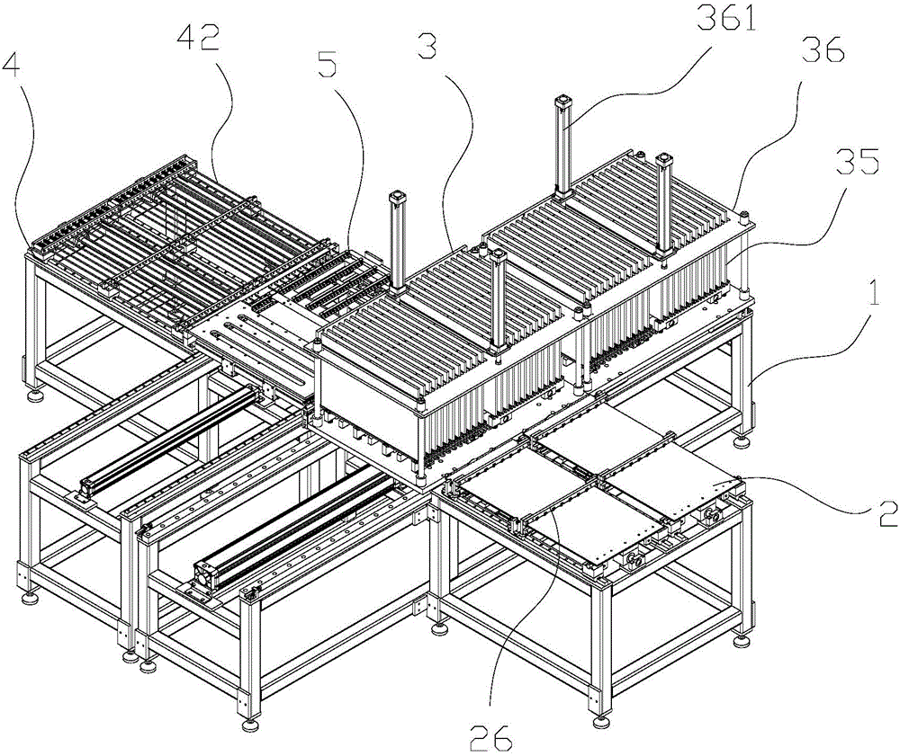
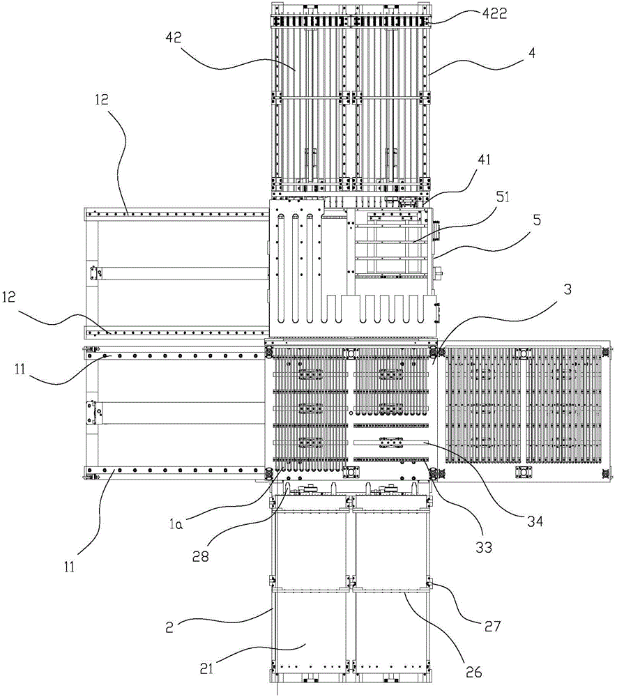
[0054] Refer to attached figure 1 to attach figure 2 As shown, a device for condenser fins to pass through copper tubes, including a bracket 1 and a push plate drive system 2 located on the bracket 1, a copper tube collector 3, a fin collector pan 5 and a traction device 4 .

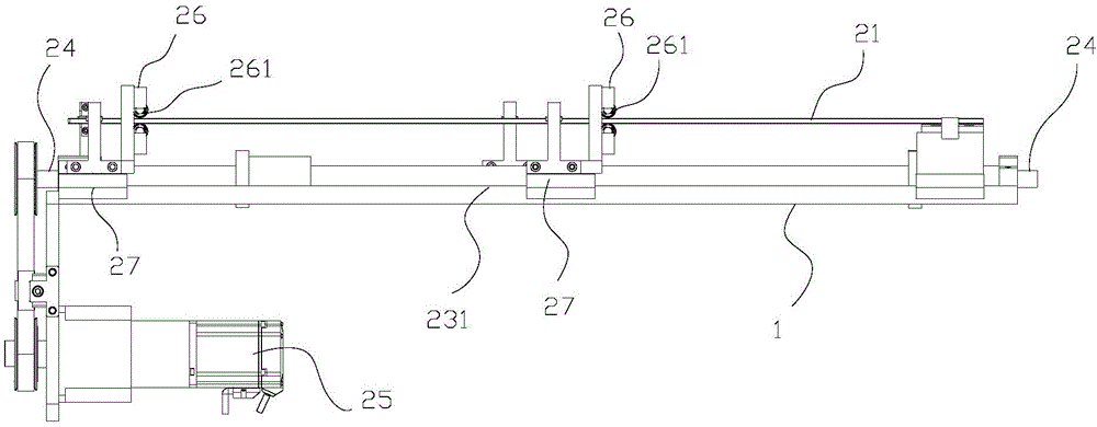
[0055] Refer to attached image 3 to attach Figure 8 As shown, the push pedal drive system 2 includes a push pedal 21 , a push pedal guide mechanism, a screw rod 24 and a motor 25 . The length c of the push plate 21 is greater than the length d of the copper pipe 1a it pushes, and the front end of the push plate 21 has a corrugated structure. The wave structure is formed by connecting the first arc segment 211 and the second arc segment 212 at intervals in sequence, the transition between the first arc segment 211 and the second arc segment 212 is smooth, and the firs...


PUM


Abstract

The invention discloses equipment for enabling a copper pipe to pass through a fin of a condenser. The equipment comprises a support, as well as a push plate driving system, a copper pipe collector, a fin collecting disc and a traction device which are sequentially positioned on the support, wherein the copper pipe is placed on a supporting base of the copper pipe collector, and clearance layers formed between clapboards or partition posts are stacked; a push plate passes through the upper part of the supporting base which can reciprocate up and down so as to push the copper pipe into the fin hole of the fin collecting disc; meanwhile a draw rod enters into the fin hole from the other side of the fin collecting disc under the effect of a guide mechanism, so as to draw the copper pipe, and a drawing head is inserted into the opening end of the copper pipe; when the draw rod is retreated from the fin hole, the copper pipe is synchronously guided into the fin hole, after that, the push plate and the draw rod are reset, the upper-layer copper pipe orderly falls to the supporting base so as to be subjected to the next round of pipe passing. The equipment is simple in operation and high in stability and safety, and can be used for improving the pipe passing efficiency and the alignment accuracy, reducing the equipment stagnation period in a pipe passing process and reducing the human cost and the equipment loss.

Description

technical field [0001] The invention belongs to the field of processing equipment for air-conditioning condensers, and in particular relates to equipment for fins passing through copper tubes of condensers. Background technique [0002] The air conditioner condenser includes a fin set and U-shaped copper tubes passing through the fin set, so threading copper tubes on the condenser fins is an important link in the preparation of the air conditioner. The traditional main process of threading tubes on fins is to rely on special feeders to automatically and neatly stack them into fin layers, and use high-speed punching machines to automatically punch fin holes on the fins for copper tubes to pass through. Grasp the copper tubes manually or with a robot, and then manually insert the U-shaped copper tubes one by one into the fin channel formed by aligning the fin holes of multiple rows of fins. When the size of the copper pipe is short, it is easy to cause work-related accidents ...

Claims


Application Information

Patent Timeline
Patent Type & Authority Applications(China)
IPC IPC(8): B23P19/00
CPCB21D53/02
Inventor 徐桂明
Owner 广州绅特模具制造有限公司
Why Eureka
Try Eureka