Centrifugal stirring optical lens polishing equipment

An optical lens, stirring technology, which is used in grinding/polishing equipment, metal processing equipment, optical surface grinders, etc., can solve the problems of no stirring mechanism and poor polishing effect, and achieve improved stability, good polishing effect, Efficient effect

Active Publication Date: 2015-01-28
南京蔚蓝新材料科技有限公司
View PDF10 Cites 2 Cited by
  • Summary
  • Abstract
  • Description
  • Claims
  • Application Information

AI Technical Summary

Problems solved by technology

[0006] The purpose of the present invention is to solve the above-mentioned problems in the prior art, and provide a centrifugal stirring optical lens polishing equipment, which has good polishing e

Method used


Image

  • Centrifugal stirring optical lens polishing equipment
  • Centrifugal stirring optical lens polishing equipment
  • Centrifugal stirring optical lens polishing equipment

Examples


Embodiment Construction

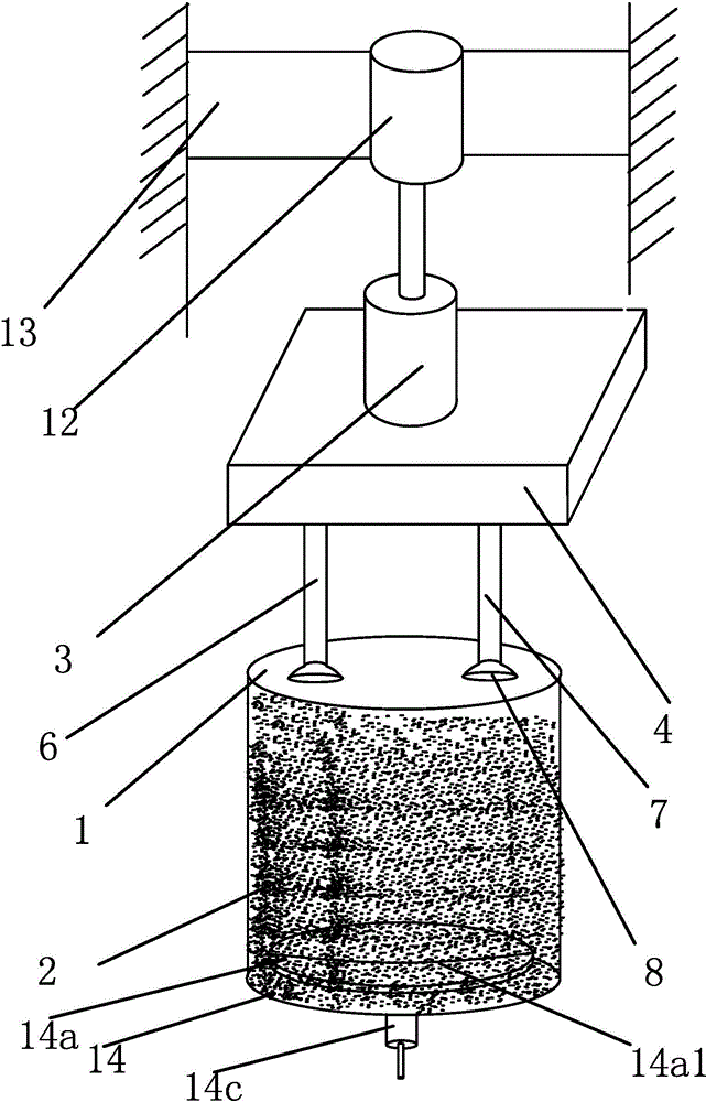
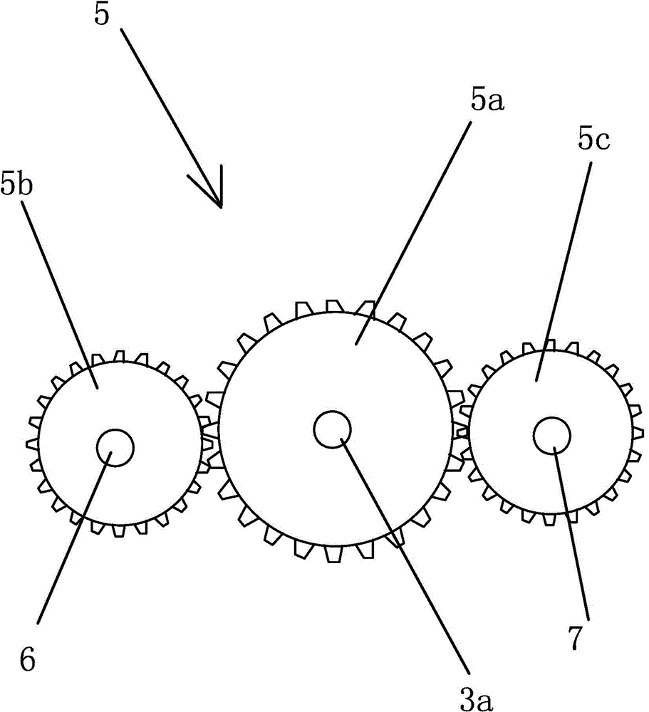
[0037] like Figure 1 to Figure 6As shown, the centrifugal stirring type optical lens polishing equipment includes a barrel-shaped processing barrel 1, which has a polishing liquid 2 in the processing barrel 1, and the polishing liquid 2 is a mixture of water and carborundum. Rotating device, rotating device comprises rotating motor one 3, and the motor rotating shaft 3a of rotating motor one 3 stretches in a square two-way box 4, and the end of motor rotating shaft 3a is connected with steering mechanism 5, and steering mechanism 5 rotates by motor rotating shaft 3a The output drives straight rod one 6 and straight rod two 7 to rotate in the opposite clockwise direction, straight rod one 6 and straight rod two 7 are arranged in parallel, the inner ends of straight rod one 6 and straight rod two 7 are connected to steering mechanism 5, and straight rod one 6 and the outer end port of straight rod two 7 are fixedly connected with suction cup 8, and steering mechanism 5 includes...


PUM


Abstract

The invention provides centrifugal stirring optical lens polishing equipment and belongs to the field of machining of an optical lens. The polishing equipment comprises a machining barrel with polishing liquid and a rotary motor I; a rotary shaft of the motor extends into a bidirectional box; the end part of the rotary shaft of the motor is connected with a steering mechanism; the steering mechanism drives a straight rod I and a straight rod II to rotate in opposite clock directions; suckers are connected to the outer ends of the two straight rods; the steering mechanism comprises a gear I, a gear II and a gear III; the gear II and the gear III are meshed with the gear I respectively; the rotary shaft of the motor is tightly matched in a bearing I and the gear I; the inner ends of the straight rod I and the straight rod II are respectively tightly matched with the gear II and the gear III; a linear motor connected with the rotary motor I is arranged above the rotary motor I; a carrier plate is arranged at the bottom of the machining barrel; a rotary motor II is connected to one side of the carrier plate and is connected with a linear motor II; a straight line shaft of the linear motor II is fixedly connected with a shell of the rotary motor II. The polishing equipment is good in polishing effect and efficient and has a stirring function.

Description

technical field [0001] The invention belongs to the field of optical lens processing equipment, and relates to a centrifugal stirring type optical lens polishing equipment. Background technique [0002] The glass originally used to make lenses is the bump on ordinary window glass or wine bottles, which is shaped like a "crown", hence the name crown glass or crown glass. The glass at that time was extremely uneven and foamy. In addition to crown glass, there is another flint glass that contains more lead. Around 1790, Frenchman Pierre-Louis Junard discovered that stirring glass sauce could make glass with uniform texture. In 1884, Ernst Abbe and Otto Schott of Zeiss Company founded the Schott Glass Factory (Schott Glaswerke AG) in Jena, Germany, and developed dozens of optical glasses within a few years, among which high refractive index The invention of the barium crown glass is one of the important achievements of SCHOTT Glassworks. [0003] Optical lenses are widely us...

Claims


Application Information

Patent Timeline
IPC IPC(8): B24B13/00
CPCB24B13/00
Inventor 王小清
Owner 南京蔚蓝新材料科技有限公司
Why Eureka
Try Eureka