Aluminum alloy ring part spray-quenching equipment and using method thereof

A technology of quenching equipment and ring parts, which is applied in the direction of quenching devices, heat treatment equipment, furnaces, etc., can solve the problems of difficult to meet the cooling strength of the side, difficult to ensure the uniformity of quenching of components, and large floor space. control, stable product quality and strong cooling capacity

Active Publication Date: 2015-01-28
CENT SOUTH UNIV
View PDF5 Cites 12 Cited by
  • Summary
  • Abstract
  • Description
  • Claims
  • Application Information

AI Technical Summary

Problems solved by technology

The solution partly solves the defects of the traditional quenching method for aluminum alloy ring parts, but it still has the following disadvantages: the heating furnace is cylindrical, and for ring parts, the invalid heating cavity is large, which wastes energy; the heating furnace and quenching furnace are arranged horizontally , covers a large area, and has a long transfer path. Additional equipment is required to transfer the ring from the heating zone to the spray quenching zone. The transfer time is long and the repeatability is poor; the axial height of common aerospace aluminum alloy rings is much greater than the section thickness, but In this device, the nozzle sprays the cooling medium from the upper and lower directions of the axial direction of the ring to the end face and side of the ring, which makes it difficult to meet the cooling intensity of the side and ensure the uniformity of quenching of the components.
The above problems become more prominent as the diameter of the aluminum alloy ring increases

Method used


Image

  • Aluminum alloy ring part spray-quenching equipment and using method thereof
  • Aluminum alloy ring part spray-quenching equipment and using method thereof
  • Aluminum alloy ring part spray-quenching equipment and using method thereof

Examples


Embodiment Construction

[0027] The structural principle and working principle of the present invention will be described below in conjunction with the accompanying drawings and a specific example.

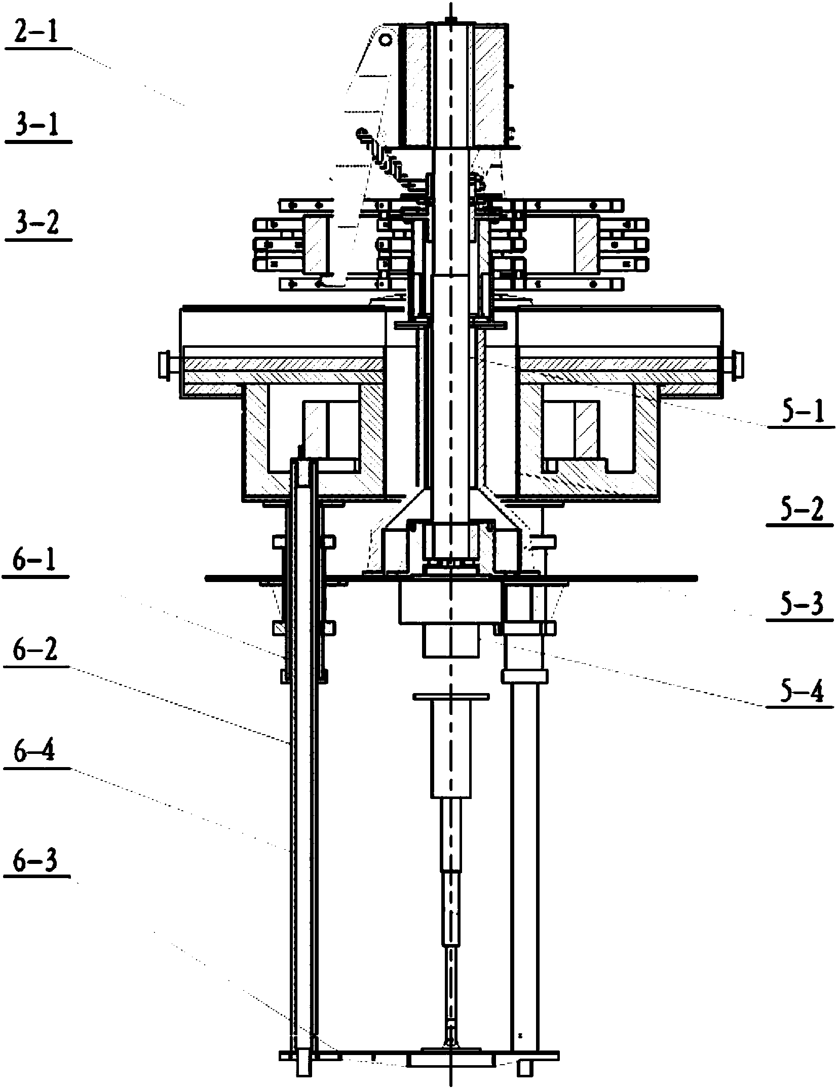
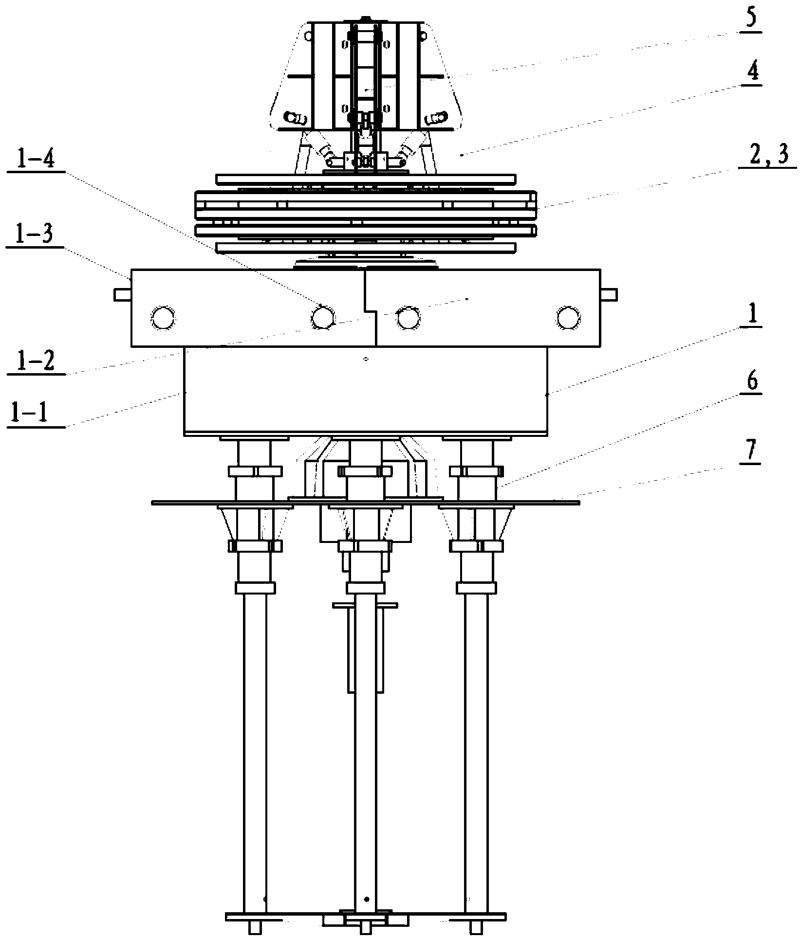
[0028] figure 1 and figure 2 Shown is a specific embodiment of the present invention, an aluminum alloy ring piece spray quenching equipment, mainly including a ring heating furnace 1, an inner spray system 2, an outer spray system 3, a support system 4, a rotating system 5, Transfer system 6, automatic control system (not reflected in the figure); wherein, the annular heating furnace 1 is used for heating the annular parts, and is placed flat on the horizontal installation surface 7 at the bottom of the furnace body. It is an annular structure with small invalid space and saves Increase energy, improve the uniformity of temperature distribution in the heating furnace, and the furnace mouth is upward, which is convenient for the transfer of ring parts between the ring heating furnace and the quenching z...


PUM


Abstract

The invention discloses aluminum alloy ring part spray-quenching equipment and a using method thereof. The aluminum alloy ring part spray-quenching equipment mainly comprises an annular heating furnace, a spraying system, a supporting system, a rotating system, a transfer system and an automatic control system, wherein a quenching area formed by the spraying system and a heating area formed by the annular heating furnace are arranged with one above the other; the annular heating furnace is annular, and a fire hole is formed in the upper end of a furnace body; the spraying system comprises an inner spraying system and an outer spraying system, a ring part is arranged in the spraying system, and the spraying system is arranged over the annular heating furnace, and is divided into six independently-controllable spraying parts for cooling corresponding areas of the ring part respectively to realize the divisional and staged cooling intensity control of the system; during quenching, the ring part is supported by the supporting system, and the supporting system and the rotating system cooperatively work to drive the ring part to rotate; the transfer system is arranged under the annular heating furnace; a support rod extends into the furnace to integrally connect the annular heating furnace with the spraying system to transfer the aluminum alloy ring part between the quenching area and the heating area.

Description

technical field [0001] The invention relates to a quenching equipment, in particular to a spray quenching equipment for an aluminum alloy ring piece, and also relates to a method for using the spray quenching equipment for an aluminum alloy ring piece. Background technique [0002] Aluminum alloy ring parts are the key connecting parts of launch vehicles and aircrafts. The diameter is generally 1-10m. In order to improve the comprehensive performance of the product, such as strength, toughness, wear resistance, stability, etc., solid solution quenching is required. However, after the aluminum alloy ring parts are solution quenched, large residual stress is generated and unevenly distributed, which causes heat treatment and subsequent processing deformation of the ring parts, and reduces the service performance and fatigue life of the material. For example, the high-strength aluminum alloy ring (Φ1000mm) is the key part of the aircraft connection. After the ring is quenched, ...

Claims


Application Information

Patent Timeline
Patent Type & Authority Applications(China)
IPC IPC(8): C21D1/667
CPCC21D1/667C21D9/40
Inventor 易幼平张玉勋崔金栋谭波黄始全
Owner CENT SOUTH UNIV
Why Eureka
Try Eureka