Targeted domain-control grouting device and grouting process

A grouting device and grouting technology, which are used in shaft equipment, shaft lining, tunnel lining, etc., can solve the problems of not having double-liquid mixing in the hole, running the slurry at the port of the mold bag, and not installing a hoop device, etc. Strength and impermeability, guaranteed fluidity, wide application effect

Active Publication Date: 2015-01-28
SHANDONG UNIV OF SCI & TECH
View PDF6 Cites 15 Cited by
  • Summary
  • Abstract
  • Description
  • Claims
  • Application Information

AI Technical Summary

Problems solved by technology

This invention has the following deficiencies: (1) it can only be used for single-liquid grouting, and cannot pour double-liquid grout, especially it does not have the function of mixing two liquids in the hole; (2) the grouting pipe 1 is fixed by a rapid hardening cement roll , can only be used for drilling grouting with a hole depth less than 10m, and cannot complete drilling grouting at any depth
This invention has the following deficiencies: (1) the invention mainly solves the problem of water stop at the orifice, and does not involve the field of grouting; (3) There is no clamping device installed between the cylindrical mold bag and the casing, but simply tied, which may easily cause the mold bag to fall off during the construction process. Or the port of the mold bag runs out of pulp, and the water-stop effect cannot be achieved

Method used


Image

  • Targeted domain-control grouting device and grouting process
  • Targeted domain-control grouting device and grouting process
  • Targeted domain-control grouting device and grouting process

Examples


Embodiment Construction

[0034] The present invention will be further described below in conjunction with the accompanying drawings and embodiments.

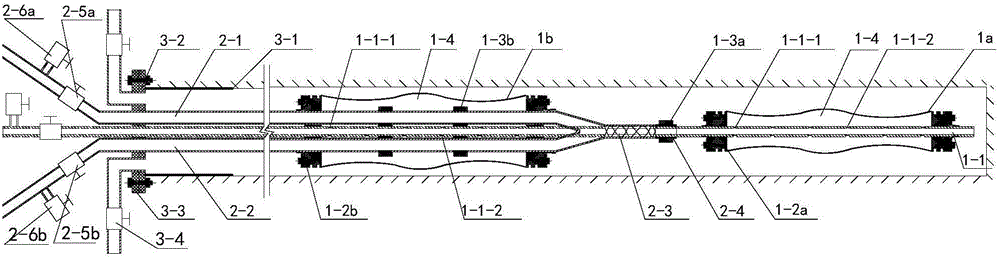
[0035] Such as figure 1 As shown, a fixed-point control area grouting device has an adaptive grouting barrier unit, a mixed double-liquid grouting unit in the hole, and an orifice fastening and sealing unit. The self-adaptive grout blocking unit is composed of a front blocking part 1a and a rear blocking part 1b, both of which are composed of a mold bag grouting pipe 1-1, a clamp, a lock, and a mold bag 1-4. The mixed double-fluid grouting unit in the hole is composed of a cement-based grouting pipe 2-1, a control liquid grouting pipe 2-2, a mixer 2-3, a short slurry outlet pipe 2-4, a grouting valve and a discharge valve. Pressure valve composition. The orifice fastening and sealing unit is composed of an orifice pipe 3-1, an orifice flange 3-2, a fastening flange 3-3 and a drain control valve 3-4.

[0036] Such as figure 1 As shown, the mold bag g...


PUM


Abstract

The invention discloses a targeted domain-control grouting device which comprises a mold-bag grouting pipe, a cement-based slurry grouting pipe and a control-liquid grouting pipe. The mold-bag grouting pipe, the cement-based slurry grouting pipe and the control liquid grouting pipe are fixed and respectively penetrate an orifice fastening and sealing unit. At least one mold bag externally sleeving the mold-bag grouting pipe is arranged on the same, a plurality of grout vents for adhering aluminum sheets are formed in the pipe wall of each mold-bag grouting pipe inside the mold bags, and when number of the mold bags is larger than one, spacing is formed among the mold bags, and spacing sections just correspond to key grouting parts of the grout vents; the cemented-based slurry grouting pipe and the tail end of the control-liquid grouting pipe are communicated to a mixer, a slurry-outlet short pipe is connected on the mixer, the slurry outlet of the slurry-outlet short pipe corresponds to the key grouting parts in the grout vent. The invention further discloses a grouting process utilizing the targeted domain-control grouting device. By the arrangement, targeted domain-control grouting on the key grouting parts is realized, mobility of double-liquid slurry initially grouted to stratum is guaranteed by mixing double liquid in the holes, the slurry can be sufficiently grouted in the key grouting parts, and overall effect of grouting engineering is improved.

Description

technical field [0001] The invention belongs to the grouting reinforcement and water blocking technology of underground engineering such as mines and tunnels, in particular to a fixed-point control area grouting device and a grouting process. Background technique [0002] At present, in the construction of underground projects such as mines and tunnels, problems such as large deformation of surrounding rocks and large amounts of water inflow often occur, and even water and mud inrush disasters may occur, causing huge loss of personnel and property. Grouting, as an effective means of strengthening weak surrounding rock and controlling water damage, has been more and more widely used in underground engineering disaster control. The practice of grouting shows that it is often some key geological sections that affect the effect of grouting reinforcement or water blocking, such as large water-conducting fissures, broken sections, karst channels, and deep areas of grouting holes (...

Claims


Application Information

Patent Timeline
Patent Type & Authority Applications(China)
IPC IPC(8): E21D11/10E21B33/13
CPCE21B33/13E21D11/105E21D11/38
Inventor 张伟杰魏久传尹会永谢道雷
Owner SHANDONG UNIV OF SCI & TECH
Why Eureka
Try Eureka