Heat dissipation system for stage lamps and stage lamps using the system and its heat dissipation method

A technology for cooling systems and lamps, applied in lighting applications, installations for theaters and circuses, lighting and heating equipment, etc. Large convection area and heat dissipation area, large heat transfer coefficient of the whole system, and the effect of improving the use effect

Active Publication Date: 2019-07-23
GUANGZHOU HAOYANG ELECTRONICS CO LTD
View PDF7 Cites 0 Cited by
  • Summary
  • Abstract
  • Description
  • Claims
  • Application Information

AI Technical Summary

Problems solved by technology

This structure uses forced convection for cooling and heat dissipation. Although the heat dissipation effect is better than that of natural convection and the above-mentioned heat dissipation methods, it still has the following defects: (1) The structure around the dichroic reflector is relatively compact, and there are many hindering factors , the fluid resistance is large, and the cooling airflow cannot circulate smoothly. In the process of forced convection, the convection coefficient h is low, the heat transfer Q of the fluid air is small, the temperature of the entire lamp holder system rises, the system thermal resistance R is large, and the whole system The heat dissipation efficiency is poor, which cannot well meet the heat dissipation requirements of the stage lighting. The heat generated by the light source part of the stage lighting cannot be discharged in a timely manner when it is in operation. The operating effect, normal service life, reliability and stability of the lighting are all affected. Seriously affected; (2) Although the heat sink disclosed in this patent can absorb most of the infrared light, there is still a part of the infrared light that is not absorbed and transmitted, which makes the temperature of the relevant components of the lamp rise; and the radiation of the light source will also be reflected The mouth is transmitted, thus affecting the effect of the lamps and lanterns

Method used


Image

  • Heat dissipation system for stage lamps and stage lamps using the system and its heat dissipation method
  • Heat dissipation system for stage lamps and stage lamps using the system and its heat dissipation method
  • Heat dissipation system for stage lamps and stage lamps using the system and its heat dissipation method

Examples


Embodiment 1

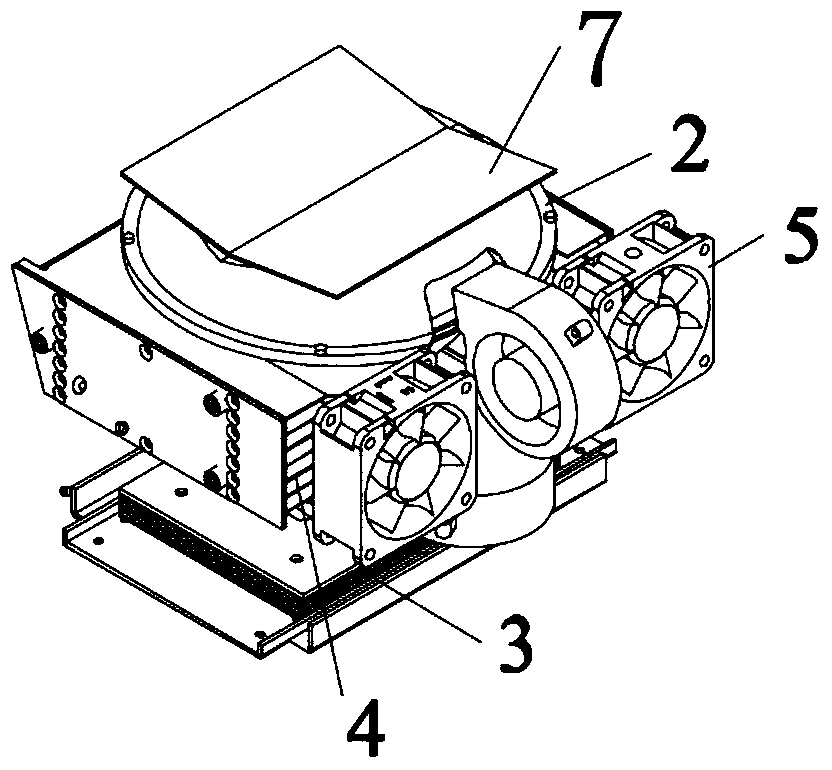
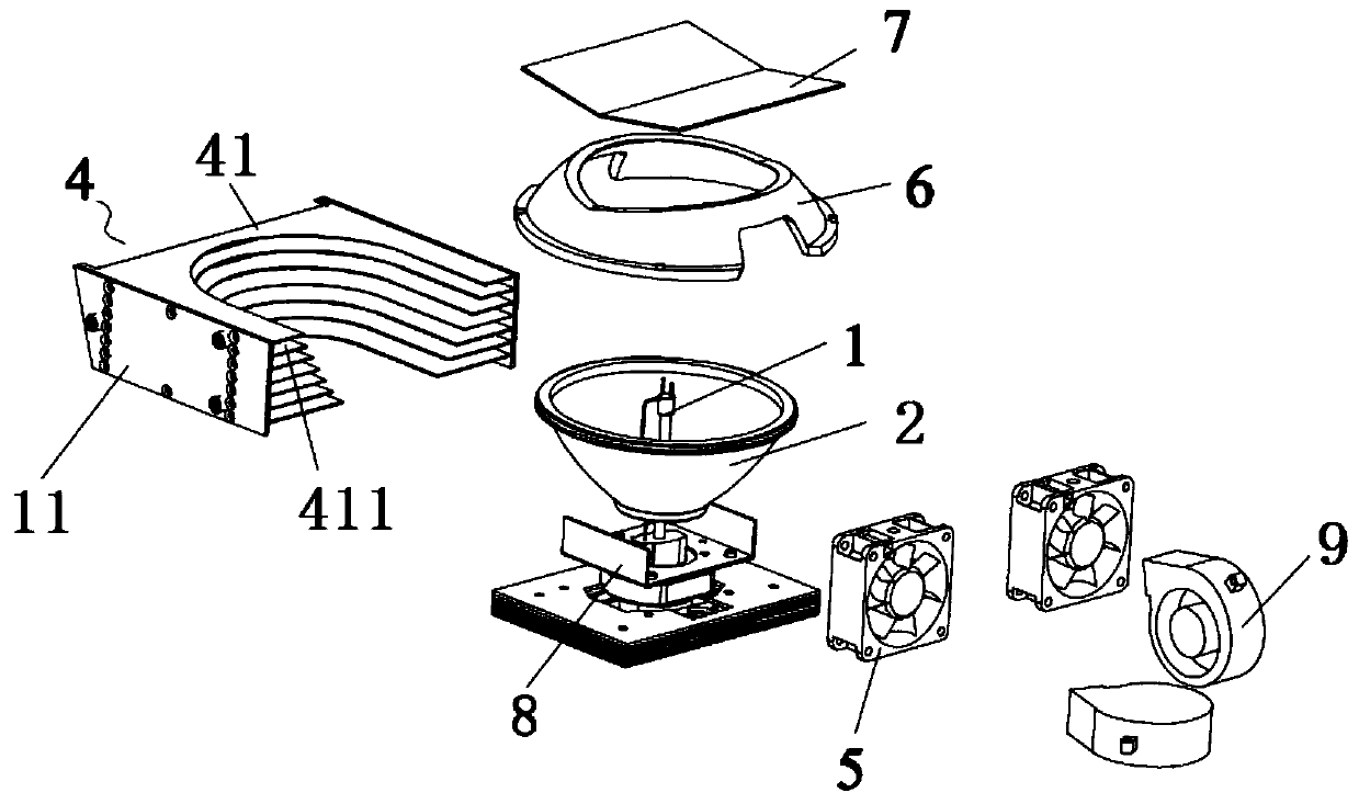
[0047] Such as Figures 1 to 6 Shown is the first embodiment of the heat dissipation system of the stage lamp of the present invention and the stage lamp and its heat dissipation method using the system, as figure 1 As shown, the heat dissipation system for stage lamps includes a light source 1, a first reflective assembly 2 surrounding the light source 1, and a fixing seat 3 for fixing the light source 1. The first reflective assembly 2 is a bowl-shaped structure or other structures; the heat dissipation system also It includes a heat dissipation component 4 surrounding the outer circumference of the first reflective component 2, the heat dissipation component 4 matches the shape of the first reflective component 2, preferably the heat dissipation component 4 is bonded to the first reflective component 2, of course, the heat dissipation component 4 can also be It is not attached to the first reflective component 2; the heat dissipation component 4 is formed by stacking a plur...

Embodiment 2

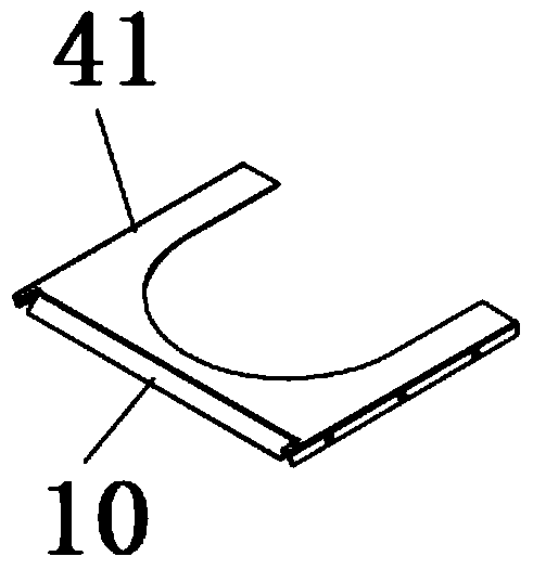
[0065] Such as Figure 7 to Figure 9 As shown, this embodiment is similar to Embodiment 1, except that the opening direction of the air duct 411 is inclined to the first reflective assembly 2 , and each air duct 411 is inclined to the central axis of the first reflective assembly 2 .

[0066] In this case, preferably, each air duct 411 is arranged tangentially along the outer circumferential surface of the first reflective assembly 2; in this way, on the one hand, the convection area between the air ducts 411 can achieve a larger convection area, which increases the heat dissipation area and has a large heat exchange area, which can effectively discharge the heat generated by the light source 1 in time and play a good heat dissipation effect; The outer peripheral surface of the first reflective component 2 is closer to adhering, which can effectively absorb infrared light, so that the infrared light can be transmitted as little as possible, so as to prevent other components of...

Embodiment 3

[0069] This embodiment is similar to the first embodiment, except that the heat dissipation assembly 4 is composed of two parts, that is, the heat dissipation fin 41 of the heat dissipation assembly 4 is composed of two halves of the heat dissipation fin units.


PUM


Abstract

Disclosed are a stage lamp heat dissipation system, a stage lamp using the system and a heat dissipation method thereof. The stage lamp heat dissipation system comprises a light source (1), a first light reflecting assembly (2) surrounding the light source (1), a fixing seat (3) for fixing the light source (1), and a heat dissipation assembly (4) surrounding the outer circumferential surface of the first light reflecting assembly (2); the heat dissipation assembly (4) is formed by stacking up a plurality of heat sinks (41), and there are gaps between the plurality of stacked adjacent heat sinks (41), so as to form an air duct (411) for airflow circulation; the air duct (411) is formed in such a manner that there is an air inlet at one end and an air outlet at the other end and the air inlet and the air outlet are directly communicated with each other; an air feed device (5) is arranged at the position of the air inlet of the air duct (411). With such an arrangement, a cooling airflow fed by the air feed device (5) flows annularly along the air duct (411) and comes into direct contact with the outer circumferential surface of the first light reflecting assembly (2); fast heat exchange of the cooling airflow with the first light reflecting assembly (2) and the light source (1) can be achieved, enabling the heat produced at the light source (1) during operating to be discharged timely and effectively.

Description

technical field [0001] The present invention relates to the technical field of stage lights, and more specifically, to a heat dissipation system for stage lights, a stage light using the system and a heat dissipation method thereof. Background technique [0002] In the field of stage lighting, the power of the stage lamps used is usually relatively large, especially the light source part, such as a stage lamp that uses a gas discharge lamp as the light source. This type of light source is restricted by the technical characteristics of the light source itself during operation. It can convert a small part of electric energy into visible light, and most of the electric energy is converted into heat, infrared rays, ultraviolet rays, etc., so that a large amount of heat is often generated during work, and then the heat is transferred to the light source, which makes the light source (such as a light bulb) overheated. High, which will affect the use effect and service life of the ...

Claims


Application Information

Patent Timeline
Patent Type & Authority Patents(China)
IPC IPC(8): F21V29/505F21V29/76F21V29/67F21S8/00F21W131/105F21W131/406
CPCF21V29/505
Inventor 蒋伟楷
Owner GUANGZHOU HAOYANG ELECTRONICS CO LTD
Why Eureka
Try Eureka