On-line monitoring apparatus of ship mooring force and monitoring method thereof

A monitoring device, a technology for mooring force, applied in the direction of tension measurement, etc., can solve the problems of expensive purchase, troublesome installation, and inability to accurately measure

Inactive Publication Date: 2015-01-28
ZHEJIANG OCEAN UNIV
View PDF7 Cites 16 Cited by
  • Summary
  • Abstract
  • Description
  • Claims
  • Application Information

AI Technical Summary

Problems solved by technology

For example, the "Stress Monitoring Device and Manufacturing Method" disclosed in the Chinese invention application with the application publication number CN103837273A (application number 201410070085.0), the stress monitoring device realizes real-time monitoring of stress changes, and the manufacturing method of the stress monitoring device solves the pro

Method used


Image

  • On-line monitoring apparatus of ship mooring force and monitoring method thereof
  • On-line monitoring apparatus of ship mooring force and monitoring method thereof
  • On-line monitoring apparatus of ship mooring force and monitoring method thereof

Examples


Embodiment 1

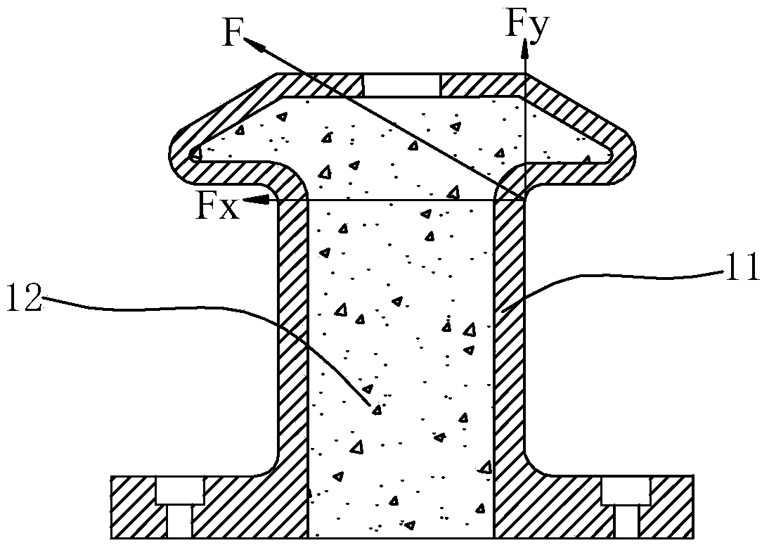
[0039] Such as Figure 1 to Figure 6 As shown, a kind of ship mooring force online monitoring device in the present embodiment includes the strain electric measuring device installed on the bollard 1, and the strain bridge signal conditioning connected with the strain electric measuring device device 3, a power supply connected to the strain bridge signal conditioner 3, a strain signal acquisition card 4, and a terminal processor connected to the strain signal acquisition card 4.

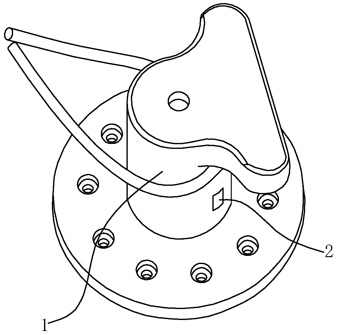
[0040] Wherein, the strain electric measuring device adopts a metal foil strain gauge 2 , and the metal foil strain gauge 2 is pasted and arranged on the column of the bollard 1 . Among them, the metal foil strain gauge 2 includes a base 21, a metal foil sensitive grid 22 arranged on the base 21, a protective sheet 23 covering the metal foil sensitive grid 22, and a signal output connector connected to the metal foil sensitive grid 22 .

[0041] The aforementioned strain bridge signal conditioner ...

Embodiment 2

[0058] The difference between this embodiment and Embodiment 1 only lies in:

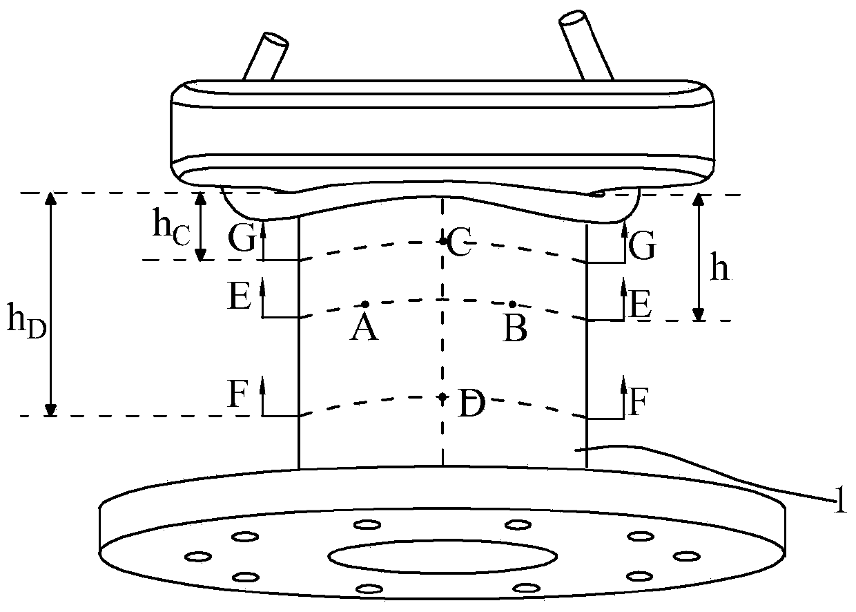
[0059] Such as Figure 7 As shown, the monitoring method of the ship's mooring force online monitoring device in the present embodiment includes the following steps:

[0060] Step 1. Select two stress monitoring points C and D on the cylindrical surface of the bollard 1 and on the same straight line parallel to the axis of the bollard 1, and fix the metal foil strain gauge 2 at the stress monitoring point C and D, wherein the base 21 of the metal foil strain gauge 2 is attached to the outer cylindrical surface of the bollard 1;

[0061] Before the metal foil strain gauge 2 is pasted, use a scraper or file to remove the oxide skin and dirt at the monitoring points C and D, and use fine sandpaper to polish a 3-5 times the area of ​​the metal foil strain gauge 2 at the monitoring point. smooth surface. During the pasting process, use absorbent cotton balls dipped in anhydrous alcohol and other solve...


PUM


Abstract

The invention relates to an on-line monitoring apparatus of a ship mooring force. The monitoring apparatus comprises a strain electrical measurement apparatus installed at a bollard, a strain bridge signal conditioner connected with the strain electrical measurement apparatus, a power supply connected with the strain bridge signal conditioner, a strain signal acquisition card connected with the strain bridge signal conditioner, and a terminal processor connected with the strain signal acquisition card. The terminal processor has a mooring force data processing unit. The provided on-line monitoring apparatus has advantages of convenient installation and low cost; and on-line real-time monitoring on the ship mooring force can be realized. In addition, the invention also designs a monitoring method of the on-line monitoring apparatus of the ship mooring force. With the method, security of the ship, the cargo, the property of the staff, and the harbor water area can be guaranteed.

Description

technical field [0001] The invention relates to the technical field of ship monitoring, in particular to an online monitoring device for ship mooring force, and also relates to a monitoring method for the online monitoring device for ship mooring force. Background technique [0002] Under the action of wind, waves, and water current, the ship will have a relatively large movement, causing unbalanced stress on the mooring cable, and even breaking the cable. The development of ship mooring force monitoring and early warning device can realize the digital detection of ship mooring force. In the existing ship mooring force monitoring technology, it is generally used to directly measure the sensor at the cut-off point or the end of the cable. Not strong and troublesome to arrange. The indirect methods of measuring the mooring force of ships are all in their infancy. The more forward-looking method is to use fiber Bragg grating sensing technology to measure the distribution of m...

Claims


Application Information

Patent Timeline
IPC IPC(8): G01L5/10
Inventor 温小飞李峰袁强卢金树祝贵兵徐宏勋
Owner ZHEJIANG OCEAN UNIV
Why Eureka
Try Eureka