Injecting device

A technology of spraying device and spraying head, applied in spraying device, spraying device, liquid spraying device, etc., can solve the problems of low spraying pressure and residual medium, and achieve the effect of increasing spraying distance, high pressure and reducing resistance

Active Publication Date: 2015-02-04
北京北机机电工业有限责任公司
View PDF11 Cites 5 Cited by
  • Summary
  • Abstract
  • Description
  • Claims
  • Application Information

AI Technical Summary

Problems solved by technology

[0003] The technical problem to be solved by the present invention is to overcome the disadvantages of low injection pressure and medium residue in the nozzle of the existing injection device, and provide an injection device that can increase the injection pressure

Method used


Image

  • Injecting device
  • Injecting device
  • Injecting device

Examples


Embodiment Construction

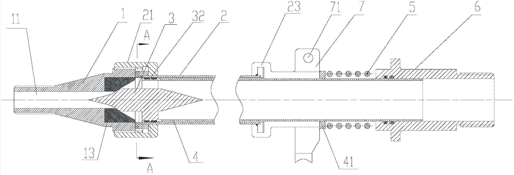
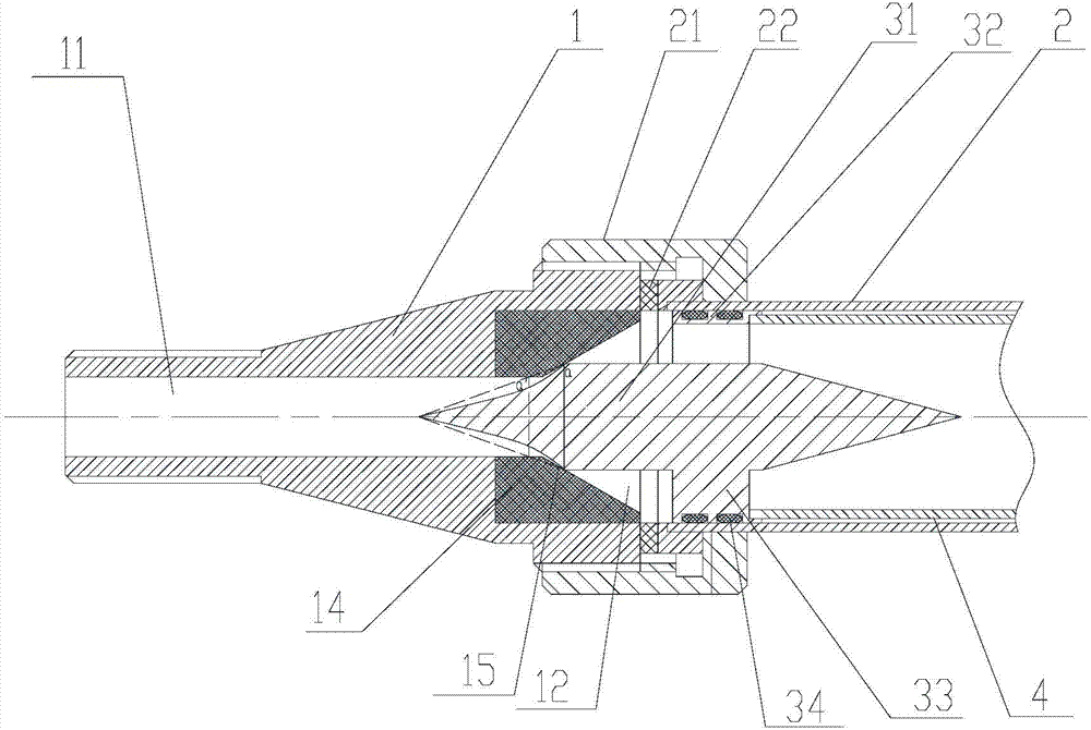
[0033] figure 1 It is a structural schematic diagram of a spraying device according to an embodiment of the present invention, figure 2 for figure 1 A partially enlarged schematic diagram of the injection device in . like figure 1 and figure 2 As shown, the spraying device of the present invention includes a spray head 1 , a spray pipe 2 , a valve core 3 and an elastic member 5 . Wherein, the spray head 1 has a spray head chamber 12 and a nozzle 11 communicating with the spray head chamber 12 , and the inner wall of the spray head chamber is provided with a valve seat 13 . In this embodiment, the valve seat 13 is arranged at the position where the nozzle cavity and the nozzle 11 meet, so that the matching position of the valve core 3 and the valve seat 13 is also at the position where the nozzle cavity and the nozzle 11 meet, When the valve core 3 is disengaged from the valve seat 13, the liquid passes through the valve seat 13 and directly enters the spout 11 to be spr...


PUM


Abstract

The invention discloses an injecting device. The injecting device comprises a spraying head, a spraying pipe, a valve core and an elastic component, wherein a valve base is arranged on the inner wall of a spraying head cavity; the front end of the spraying pipe is communicated with the rear end of the spraying head and is connected with the rear end of the spraying head in a sealing way; the valve core is moved forwards or backwards in the spraying head cavity and the spraying pipe to be matched with or depart from the valve base; the front end of a valve core body is matched with an inclination part of the valve base; the valve core body is provided with a passage parallel to an axial line of the valve core body; the elastic component can apply a force enabling the valve core to move towards the valve base and to be matched with the valve base; a trigger can apply a force enabling the valve core to be departed from the valve base. Due to the fact that the valve core is provided with the passage parallel to the axial line of the valve core body, and the liquid does not deflect in the process from the time when the liquid enters the passage to the time when the liquid enters a spraying nozzle to be sprayed out, the resistance during flowing of the liquid is greatly reduced, the pressure higher than the pressure in the prior art can be maintained when the liquid is sprayed out of the spraying nozzle, the injection distance is increased, and even a medium with relatively high viscidity is not left at the spraying nozzle.

Description

technical field [0001] The present invention relates to the field of liquid jetting. Specifically, it is a spraying device. Background technique [0002] Liquid injection is widely used in various fields. The injection device generally has a nozzle and a nozzle. The liquid enters the nozzle from the nozzle and sprays when the valve of the nozzle is opened. At present, the front end of the spool of the valve of the injection device is used to cooperate with the valve seat, and the middle or rear part of the spool is provided with a flow channel parallel to the axis of the spool. When the valve is opened, the front end of the valve core is disengaged from the valve seat, and the liquid turns to a direction parallel to the axis of the valve core after passing through the flow channel, and then sprays out through the space between the valve core and the valve seat. At present, the problem of this kind of injection device is that since the flow channel is perpendicular to the v...

Claims


Application Information

Patent Timeline
Patent Type & Authority Applications(China)
IPC IPC(8): B05B1/32B05B9/04
CPCB05B1/326
Inventor 李振兴李喆李培培郭桂容陈伟
Owner 北京北机机电工业有限责任公司
Why Eureka
Try Eureka