A positioning method for the ceramic core of a turbine blade with an integrally cast cover plate structure

A technology of ceramic cores and turbine blades, applied in the direction of molds, cores, mold components, etc., can solve the problems of difficult implementation and high positioning requirements, shorten the cycle of core removal, improve molding efficiency, and reduce waste Effect

Active Publication Date: 2016-05-18
SHENYANG LIMING AERO-ENGINE GROUP CORPORATION
View PDF7 Cites 0 Cited by
  • Summary
  • Abstract
  • Description
  • Claims
  • Application Information

AI Technical Summary

Problems solved by technology

[0004] In order to ensure that the distance L from the top of the blade cover plate to the blade reference plane meets the tolerance requirements, the positioning requirements for the ceramic core of the turbine blade with the integral cast cover plate structure are very high, and the implementation is very difficult

Method used


Image

  • A positioning method for the ceramic core of a turbine blade with an integrally cast cover plate structure
  • A positioning method for the ceramic core of a turbine blade with an integrally cast cover plate structure
  • A positioning method for the ceramic core of a turbine blade with an integrally cast cover plate structure

Examples


Embodiment Construction

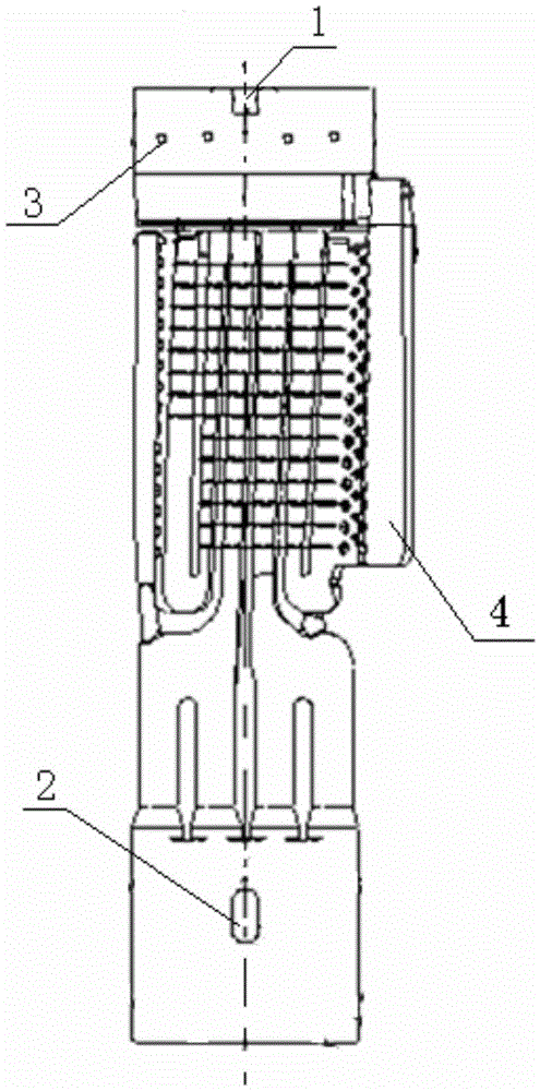
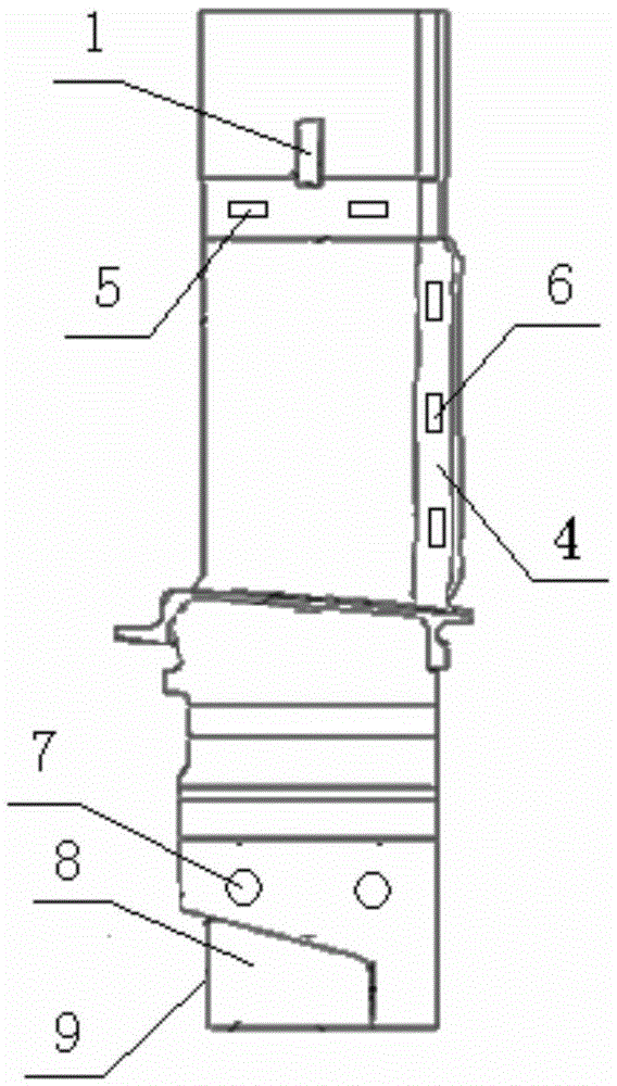
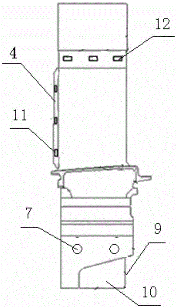
[0035] Such as Figure 1~3 As shown, a method for positioning the ceramic core of a turbine blade with integrally cast cover plate structure includes positioning the ceramic core of a turbine blade with integrally cast cover plate structure in the blade shape mold and positioning the ceramic core in the blade wax model in the ceramic mold. Two processes are located in the shell;

[0036] The positioning process of the ceramic core in the blade shape mold includes the following steps:

[0037] Step 1: Open the blade shape mold, and place the ceramic core in the cavity of the blade shape mold;

[0038] Step 2: The positioning of the ceramic core in the left and right direction in the blade shape mold: the left and right direction refers to the direction of the blade exhaust side, and the positioning bump of the blade shape mold is put into the blade tip on the ceramic core for positioning In the groove 1, insert the positioning protrusion 2 of the blade shape mold into the ten...


PUM

PropertyMeasurementUnit
diameteraaaaaaaaaa
lengthaaaaaaaaaa
widthaaaaaaaaaa

Abstract

The invention relates to a positioning method of a ceramic core of a blade, and particularly relates to a positioning method of a ceramic core of a turbine blade with a block-cast cover plate structure. According to the following technical scheme of the invention, the positioning method of the ceramic core of the turbine blade with the block-cast cover plate structure comprises two processes of positioning a ceramic core of the turbine blade with the block-cast cover plate structure in a blade shape mould and positioning the ceramic core in a blade wax mould in a ceramic shell. The invention provides a positioning method of the ceramic core of the turbine blade with the block-cast cover plate structure. Positioning of the ceramic core in the blade shape mould and in the ceramic shell is comprehensively considered in a precision casting process, the consistency of an inner outline and an outer outline is ensured, and the distance between the top end of a cover plate of the blade and a reference surface of the blade can be enabled to accord with the tolerance requirement.

Description

technical field [0001] The invention relates to a positioning method for a ceramic core of a blade, in particular to a positioning method for a ceramic core of a turbine blade with an integrally cast cover plate structure. Background technique [0002] The tip of the traditional turbine working blade is a cover-plate post-welding structure. With the improvement of engine performance, the requirements for the temperature bearing capacity of the blade are getting higher and higher. The blades of this cover-plate post-welding structure will fall off during use. , has brought hidden danger to the reliability of blade and engine. In order to improve the performance of the engine, it is necessary to manufacture turbine rotor blades with integral cast cover plate structure. [0003] The manufacture of ceramic cores is the basis for forming blades with complex inner cavity structures. The manufacture of integrally cast cover plate structure turbine working blades requires extremely...

Claims


Application Information

Patent Timeline
Patent Type & Authority Patents(China)
IPC IPC(8): B22C9/10
CPCB22C9/108
Inventor 彭志江张明俊乐献刚邹建波张泽海
Owner SHENYANG LIMING AERO-ENGINE GROUP CORPORATION
Why Eureka
Try Eureka