
Hydraulic clamping and positioning device for slope processing of connecting rod

A positioning device, hydraulic clamping technology, applied in the direction of positioning device, metal processing equipment, metal processing machinery parts, etc., can solve the problems of low processing efficiency, low efficiency, affecting processing efficiency and quality, etc., to achieve fast and stable clamping Positioning, improving production efficiency, and high production efficiency

Active Publication Date: 2015-02-04
山东盛祥智能制造有限公司
View PDF6 Cites 10 Cited by
  • Summary
  • Abstract
  • Description
  • Claims
  • Application Information

AI Technical Summary

Problems solved by technology

[0003] The positioning of the connecting rod has a manual clamping connecting rod device, which has the disadvantage of low efficiency during use
Because it takes about 20 minutes to manually position and clamp the connecting rod each time, it is obvious that the processing efficiency is very low
In order to solve the problem of low efficiency, a mechanical connecting rod processing device has appeared. Although this device has improved the production efficiency to a certain extent, its clamping and positioning of the connecting rod is unstable, resulting in that the connecting rod cannot be processed smoothly and effectively. Being cut will affect the efficiency and quality of processing

Method used


Image

  • Hydraulic clamping and positioning device for slope processing of connecting rod
  • Hydraulic clamping and positioning device for slope processing of connecting rod
  • Hydraulic clamping and positioning device for slope processing of connecting rod

Examples


Embodiment Construction

[0038] In order to make the object, technical solution and advantages of the present invention clearer, the present invention will be further described in detail below in conjunction with the accompanying drawings and embodiments. It should be understood that the specific embodiments described here are only used to explain the present invention and not to limit the present invention.

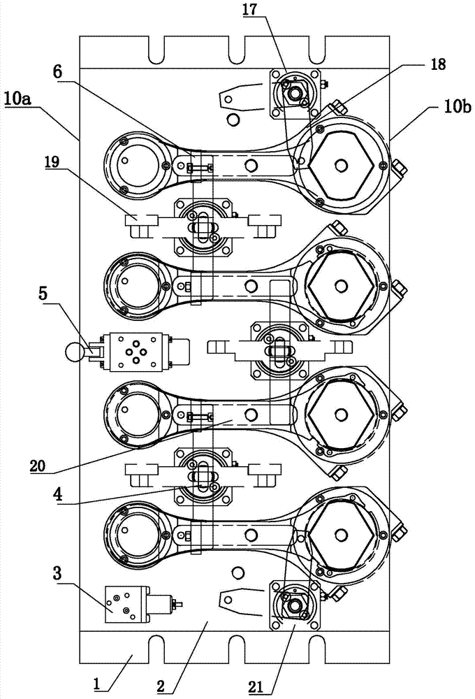
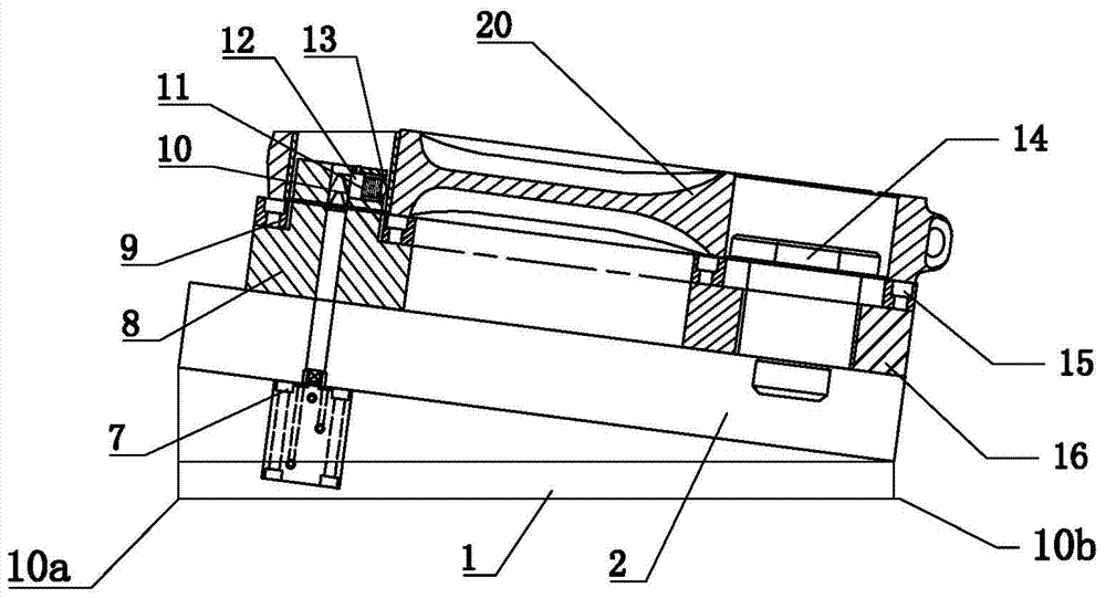
[0039] Such as figure 1 with figure 2 As shown, a hydraulic clamping and positioning device for processing inclined surfaces of connecting rods includes a bottom plate 1, which includes a first side 10a and a second side 10b oppositely arranged, wherein the first side 10a is higher than the second side 10b, and the bottom plate 1 The upper surface of 1 is provided with an inclination.

[0040] Such as figure 2 , image 3 , Figure 4 with Image 6As shown, the upper surface of the bottom plate 1 in this embodiment is provided with a fixture plate 2 , and a small end hole positioning devic...


PUM


Abstract

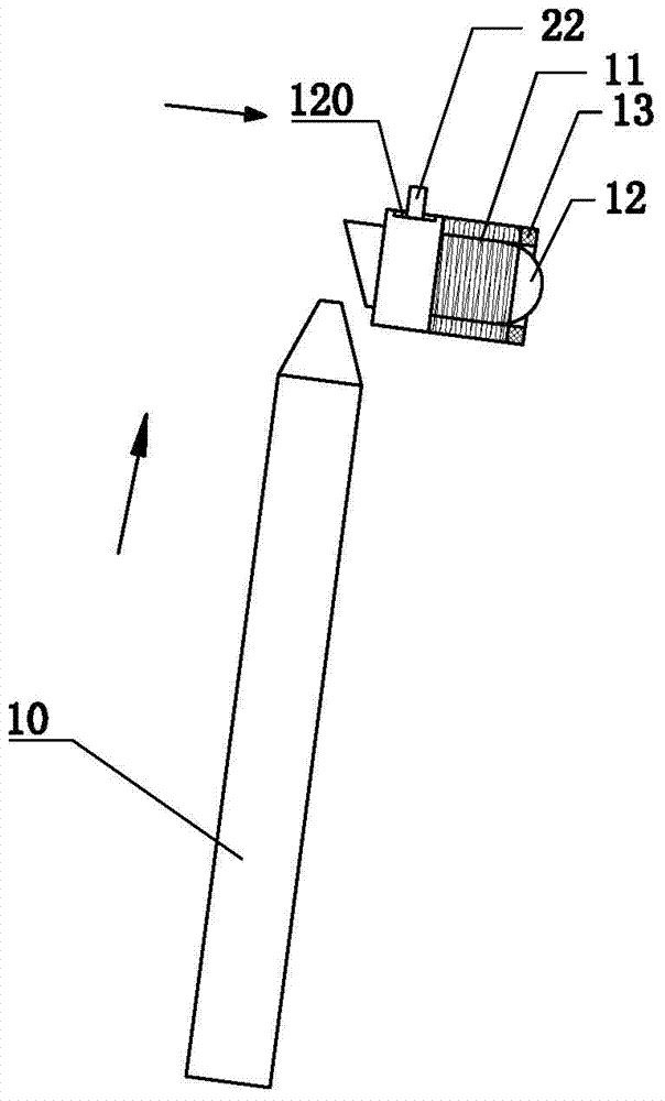
The invention discloses a hydraulic clamping and positioning device for slope processing of connecting rod. The hydraulic clamping and positioning device for slope processing of connecting rod comprises a baseboard provided with a clamp board, wherein a small end hole positioning device is arranged on the clamp board, the small end hole positioning device comprises a first cushion block provided with a first through hole, a horizontal through hole is formed in a boss of the first through hole, an ejecting column is arranged inside the horizontal through hole, a piston rod of a thin-wall oil cylinder extends from the first through hole and abuts against a cone head rod, the cone head slope of the cone head rod can push the slope of the ejecting column to position a small end hole, a large end hole positioning device comprises a second cushion block provided with a second through hole in the middle, a positioning pin of the second through hole positions a large end hole, and two single head pressing boards and a plurality of double head pressing boards are used for clamping a connecting rod. A hydraulic oil cylinder can fast position and clamp the small end hole, the large end hole is positioned by the positioning pin, the hydraulic oil cylinder also can fast control the pressing of the single head pressing boards and the double head pressing boards on the connecting rod of each working position, so that the connecting rod slope processing can be smoothly conducted, and the processing efficiency is improved.

Description

technical field [0001] The invention relates to the technical field of machining, in particular to a hydraulic clamping and positioning device for machining inclined surfaces of connecting rods. Background technique [0002] The connecting rod is a rod whose two ends are respectively hinged with the active part and the driven part to transmit motion and force. It includes a small end hole and a large end hole, and a rod connecting the small end hole and the large end hole. The small end hole of the connecting rod usually has a connecting rod bevel, which is usually machined to position the connecting rod before milling. [0003] The positioning of the connecting rod has a manual clamping connecting rod device, which has the disadvantage of low efficiency during use. Because it takes about 20 minutes to manually position and clamp the connecting rod each time, it is obvious that the processing efficiency is very low. In order to solve the problem of low efficiency, a mechan...

Claims


Application Information

Patent Timeline
Patent Type & Authority Applications(China)
IPC IPC(8): B23Q3/08
CPCB23Q3/082B23Q3/062
Inventor 孟庆杰杨文娟
Owner 山东盛祥智能制造有限公司
Learn More