Flanging mould, assembling mould, and paving method and moulding method of moulding material

A flanging mold and laying method technology, which is applied in the field of fan blade manufacturing, can solve the problems of hand lay-up air bubbles, the flanging mold is not easy to fix, and delamination, and achieve the effect of reducing air bubbles

Active Publication Date: 2015-02-04
JIANGSU GOLDWIND SCI & TECH CO LTD
View PDF4 Cites 14 Cited by
  • Summary
  • Abstract
  • Description
  • Claims
  • Application Information

AI Technical Summary

Problems solved by technology

[0008] The hand lay-up and flanging mold cannot produce a suitable flanging angle, and the flanging mold is not easy to fix; the hand lay-up and flanging is purely manual operation, and the production quality depends on the worker's operating skills, which cannot guarantee the consistency of product quality. It is quite different from the design drawings, and it is easy to cause hand-laid air bubbles and delamination problems. There will be bright spots at the corners of the flanging (the surface of the glass fiber is glowing due to the uneven penetration of the resin on the glass fiber), which affects the flanging and the fan blade. The bonding effect; the whole production process is more cumbersome and the production cycle is longer

Method used


Image

  • Flanging mould, assembling mould, and paving method and moulding method of moulding material
  • Flanging mould, assembling mould, and paving method and moulding method of moulding material
  • Flanging mould, assembling mould, and paving method and moulding method of moulding material

Examples


Embodiment 1

[0028] First introduce the flanging mold of the embodiment of the present invention below, Figure 4 It is a structural schematic diagram of the flanging mold in the combined mold of the I-shaped web of the fan blade according to the embodiment of the present invention.

[0029] Such as Figure 4 As shown, the flanging mold of the fan blade I-shaped web provided by the embodiment of the present invention has the following specific features: the flanging mold has an integrated mold surface, and the mold surface has a pointed protrusion 320, and the pointed protrusion 320 The vertex of the flange is bounded, and the first curved surface 310 and the second curved surface 330 are formed on both sides. During the molding process, the first curved surface 310 of the flanging mold is bonded to the molding material of the turned-up part of the outer flange 203, which is used for To form the shape of the turned-up portion, the second curved surface 330 of the turn-up mold is in contac...

Embodiment 2

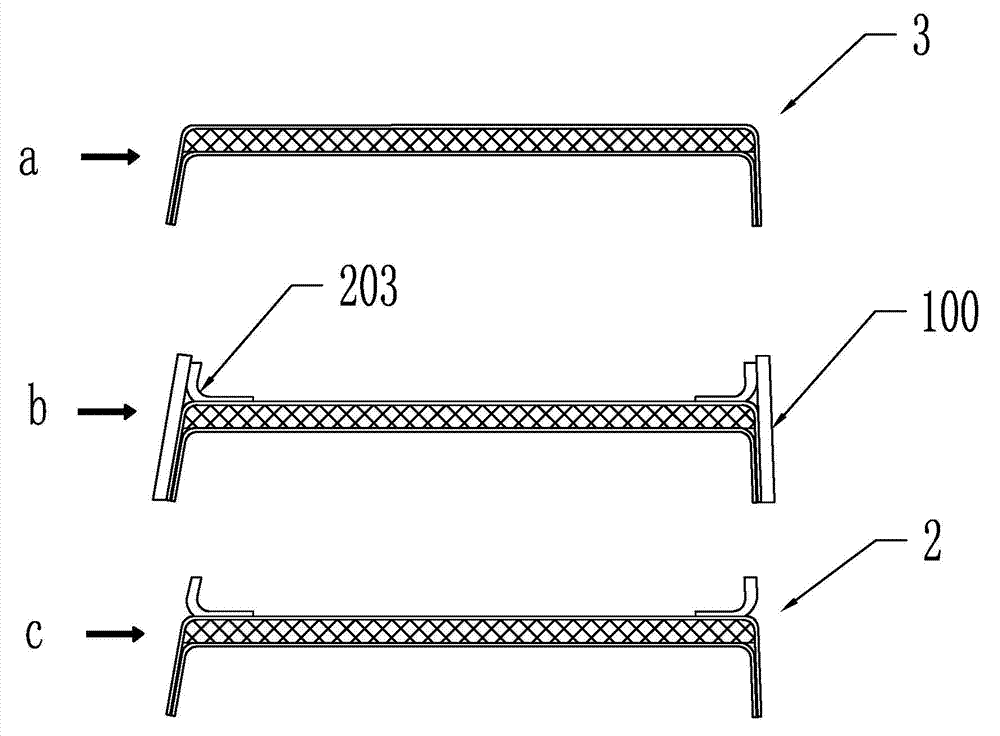
[0035] The laying method and molding method of the molding material for processing the I-shaped web of the fan blade based on the above combined mold will be introduced below.

[0036] Such as Figure 6 and Figure 8 As shown, based on the above combined mold, the flow process of the laying method of the molding material in the embodiment of the present invention is as follows:

[0037] Step 601: Lay the lower diversion net, the lower isolation film, and the first molding material for forming the web body and inward flanging in sequence on the flat mold, and the lower diversion net and the lower isolation film are covered to form the web body and inversion edge position. The state after laying is as Figure 8In process e in, the lower guide net is mainly used to guide the resin so that the resin can be evenly spread to each part of the web body and the inner flange, and the lower isolation film is used to connect the lower guide net with the first The molding material is s...

Embodiment 3

[0045] Such as Figure 7 As shown, it is a flow chart of the molding method of the fan blade I-shaped web in the embodiment of the present invention, which includes:

[0046] Step 701 of laying the film-forming material: In this step, the molding material is laid by using the laying method of the molding material in the above-mentioned embodiment 2, and the shape after laying is as follows Figure 8 Shown in process f.

[0047] Step 702 of forming a sealed perfusion space: setting a vacuum perfusion auxiliary component on the upper guide net and sealing the gap between the flanging mold and the flat mold to form a sealed perfusion space for vacuum perfusion. Among them, the vacuum auxiliary components mainly include components such as pipelines required for forming a sealed perfusion space and subsequent perfusion, such as vacuum membranes, glue injection pipelines, and vacuum pipelines. Specifically, a guide tube is arranged on the upper guide net, and a vacuum film is used...


PUM


Abstract

The invention provides a flanging mould, an assembling mould, a paving method and a moulding method of a moulding material. The flanging mould comprises a unibody mould surface, the mould surface comprises a sharp embossment, and the mould surface is divided by the climax of the sharp embossment into a first curved surface and a second curved surface. During the moulding process, the first curved surface is laminated with the film-forming material of the turn-up part of the external flanging so as to form the shape of the turn-up part; and the second curved surface is laminated with the film forming materials of partial web body and internal flanging. A combination of two flanging moulds and a plate mould is adopted so as to integrally forming the external flanging, web body, and internal flanging. The problem that the flanging angle of an I-shaped web, which is flanged manually, is not accord with the design map is avoided. Moreover, the defects such as foams, layering, and bright spots in the corner are reduced.

Description

technical field [0001] The invention relates to the technical field of fan blade manufacturing, in particular to a flanging mold for an I-shaped web of a fan blade, a combined mold, a method for laying molding materials and a molding method. Background technique [0002] In fan blades, the web is one of the main load-bearing structures. At present, the webs in fan blades are mainly I-shaped webs and C-shaped webs. Compared with C-shaped webs, I-shaped webs can better avoid stress concentration and have higher structural safety. Therefore, in large-scale I-shaped webs are mainly used in fan blades. [0003] figure 1 and figure 2 It is a schematic diagram of the position of the I-shaped web in the cross-sectional structure of the fan blade in the prior art and a structural diagram of the I-shaped web, respectively. In the fan blade, the I-shaped web 2 is attached to the fan blade through the adhesive 1 On the inner wall, the entire fan blade is supported from the inside. ...

Claims


Application Information

Patent Timeline
Patent Type & Authority Applications(China)
IPC IPC(8): B29C33/42B29C70/38
Inventor 李小明
Owner JIANGSU GOLDWIND SCI & TECH CO LTD
Why Eureka
Try Eureka