
LED smart ceiling lamp utilizing wireless (Bluetooth) control technique

A control technology, LED lamp bead technology, applied to the components of lighting devices, lighting devices, light sources, etc., can solve problems such as network dependence, not easy to popularize, and no obstacles in the middle, so as to improve operability Sex and practical value, simple and direct control, colorful effects

Inactive Publication Date: 2015-02-04
深圳市千百色光电有限公司
View PDF5 Cites 12 Cited by
  • Summary
  • Abstract
  • Description
  • Claims
  • Application Information

AI Technical Summary

Problems solved by technology

[0002] At present, the wireless control technology used in the known LED ceiling lamps is mostly controlled by the remote control. The LED ceiling lamp can be switched on and off, the brightness adjustment and simple color control can be performed by using the remote control, but the effective control distance of the remote control is relatively short during use. And there can be no obstacles in the middle, the color change is very limited, mostly limited to the change between the color temperature of white light
Secondly, there is also a wireless control technology using Wi-Fi, which can be controlled remotely using devices such as mobile phones and tablet computers, but this technology must be carried out with the help of intermediate devices such as Wi-Fi networks and gateways. Operates efficiently, is network dependent and thus less conducive to adoption

Method used


Image

  • LED smart ceiling lamp utilizing wireless (Bluetooth) control technique
  • LED smart ceiling lamp utilizing wireless (Bluetooth) control technique

Examples


Embodiment Construction

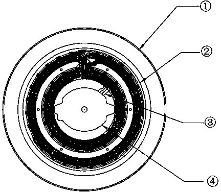
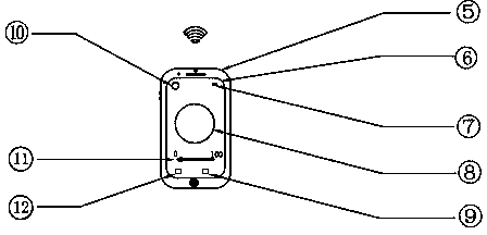
[0006] LED smart ceiling lamp ( figure 1 ) is mainly composed of LED intelligent control power supply (4), LED red, green, blue and white light PCB light board (2), and a base (1) used to fix the LED intelligent control power supply and LED red, green, blue and white light PCB light board. The intelligent control power supply includes bluetooth module, MCU and LED power driver module (the LED power driver module is divided into four groups of red, green, blue and white) and other devices. The Bluetooth module is used to receive the Bluetooth signal sent by the terminal intelligent controller (5) and transmit the signal to the MCU. The MCU processes the signal and then transmits the signal instruction to the LED power drive module. The LED power drive module passes the power output line (3) Supply power to the LED red, green, blue and white PCB light board, so as to realize the light emission of the LED red, green, blue and white light PCB light board.

[0007] Further explana...


PUM


Abstract

The invention discloses an LED smart ceiling lamp utilizing a wireless (Bluetooth) control technique. The LED smart ceiling lamp mainly comprises an LED smart control power supply and an LED red-green-blue white light PCB lamp board, wherein the LED smart control power supply internally comprises a Bluetooth module, an MCU and an LED power supply driving module; the Bluetooth module is used for receiving a Bluetooth signal sent by terminal smart controllers (such as a cell phone, a tablet personal computer) and transmitting the signal to the MCU; the MCU processes the signal and transmits the signal command to the LED power supply driving module; the LED power supply driving module supplies power for the LED red-green-blue white light PCB lamp board via a power supply output wire; the functions of switching, color modulation, luminance modulation, timing, music flash lamps and the like of the LED smart ceiling lamp can be controlled in a wireless (Bluetooth) mode; and the functions and colors of light are enriched, and the LED smart ceiling lamp has relatively high operability and practical value.

Description

technical field [0001] The invention relates to a wireless (Bluetooth) control technology for LED smart ceiling lamps, especially for the wireless control of LED smart ceiling lamps by using terminal smart controllers such as mobile phones and tablet computers without remote control or WI-FI network. control. Background technique [0002] At present, the wireless control technology used in the known LED ceiling lamps is mostly controlled by the remote control. The LED ceiling lamp can be switched on and off, the brightness adjustment and simple color control can be performed by using the remote control, but the effective control distance of the remote control is relatively short during use. And there can be no obstacles in the middle, and the color change is very limited, mostly limited to the change between the color temperature of white light. Secondly, there is also a wireless control technology using Wi-Fi, which can be controlled remotely using devices such as mobile p...

Claims


Application Information

Patent Timeline
Patent Type & Authority Applications(China)
IPC IPC(8): F21S8/04F21V23/00F21V23/04F21Y101/02
CPCF21S8/04F21V23/003F21V23/0435F21Y2101/00
Inventor 不公告发明人
Owner 深圳市千百色光电有限公司
Learn More