Axis deviation detection device and detection method

A detection device and detection method technology, applied in the direction of measuring devices, instruments, etc., can solve problems that are difficult to meet the needs of actual production

Inactive Publication Date: 2015-02-04
WUHAN WUCHUAN ELECTROMECHANICAL EQUIP
View PDF6 Cites 3 Cited by
  • Summary
  • Abstract
  • Description
  • Claims
  • Application Information

AI Technical Summary

Problems solved by technology

Therefore, this method has significant limitations and is difficult to meet the needs of actual production

Method used


Image

  • Axis deviation detection device and detection method
  • Axis deviation detection device and detection method
  • Axis deviation detection device and detection method

Examples


Embodiment 1

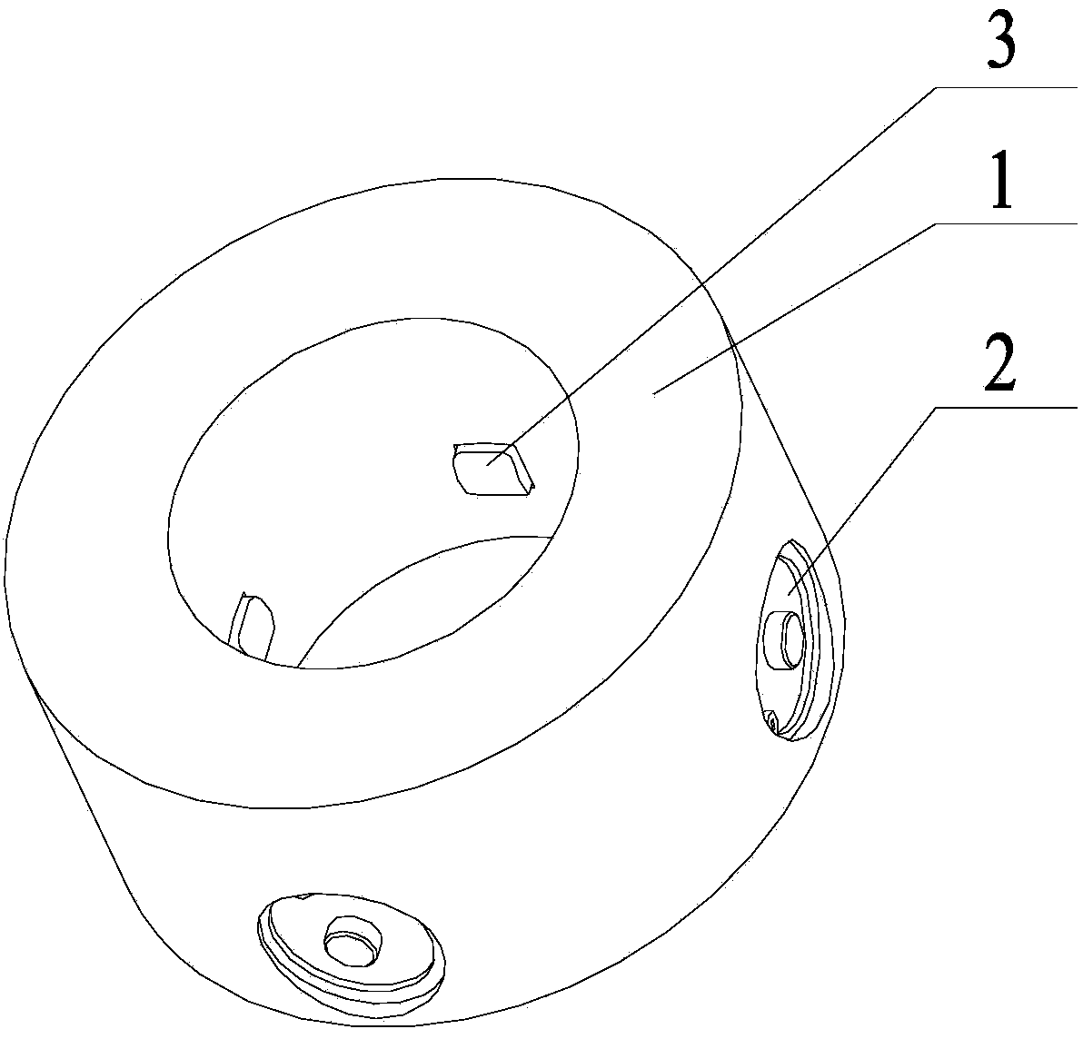
[0076] See attached figure 1 , the shaft deflection detection device provided by the present invention includes a positioning ring 1 and a detection head 2, a plurality of through holes are provided in the radial direction on the side wall of the positioning ring 1, the number of the detection heads 2 is the same as the number of the through holes, and the detection head 2 are arranged in the through hole in a one-to-one correspondence, the inner probe 3 of each detection head 2 is cocircular and coincides with the center of the positioning ring, and the inner probe of each detection head can move in the through hole.

[0077] When the shaft deflection detection device provided by the present invention is applied, the shaft to be measured passes through the center of the positioning ring 1, and each detection head 2 is moved so that the inner measuring head 3 of each detection head 2 is against the shaft to be measured. According to this The displacement of the internal measur...

Embodiment 2

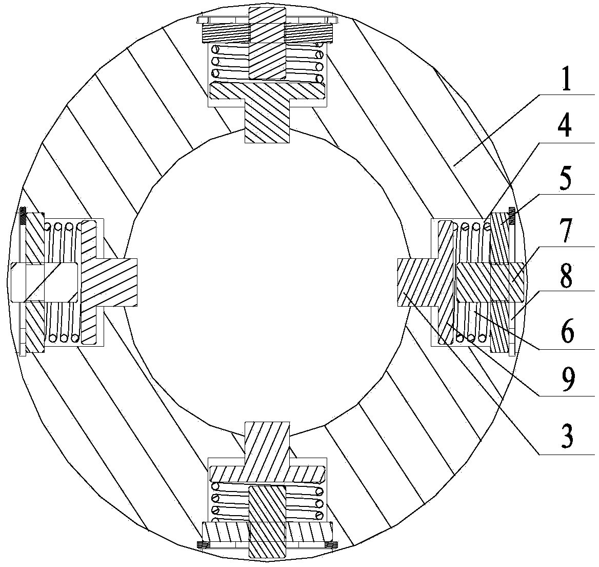
[0081] See attached Figure 2-7 , the difference from Embodiment 1 of the present invention is that the through hole of the shaft deflection detection device provided in Embodiment 2 of the present invention is a stepped hole, and the stepped hole includes three sections from the outside to the inside and the diameters are successively reduced. The detection head includes Gasket 5, column 7, elastic part 4, pressing piece 9 and internal measuring head 3, the diameter of gasket 5 is equal to the diameter of the through hole of the first section, the diameter of pressing piece 9 is equal to the diameter of the through hole of the second section, the column 7 Fixedly connected to the gasket 5, the inner diameter of the elastic part 4 is larger than the diameter of the column 7, the outer diameter of the elastic part 4 is smaller than the diameter of the second section of the through hole, the diameter of the internal measuring head 3 is equal to the diameter of the third section o...

Embodiment 3

[0084] See attached Figure 21 , the difference from the shaft deflection detection device provided in Embodiment 2 of the present invention is that the shaft deflection detection device provided in Embodiment 3 of the present invention further includes a data acquisition module, a data operation module and a data output module,

[0085] The data acquisition module is used to collect the displacement value of the internal measuring head of each detecting head;

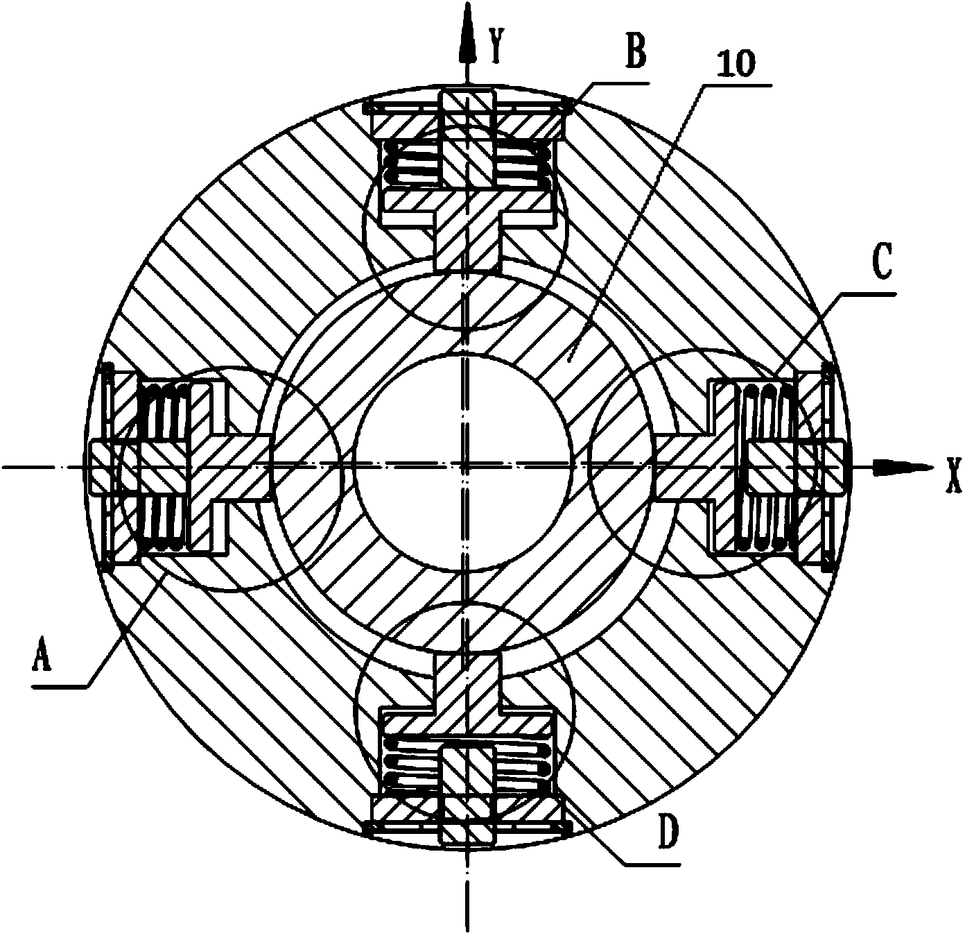
[0086] The data operation module is used to calculate the abscissa and ordinate of the center of the axis to be measured deviated from the center of the positioning ring according to the displacement of the inner probe of each detection head;

[0087] The data output module is used to output the abscissa and ordinate of the center of the shaft to be measured deviated from the center of the positioning ring.


PUM


Abstract

The invention discloses an axis deviation detection device and detection method and belongs to the technical field of detection devices. The axis deviation detection device comprises a locating ring and detection heads, a plurality of through holes are opened in the side wall of the locating ring along the longitudinal direction, the number of the detection heads is the same with that of the through holes, the detection heads are through arranged in the through holes in a one-to-one correspondence mode, the inner detection heads of the detection heads are con-cyclic and overlapped with the circle center of the locating ring, and the inner detection head of each detection head is capable of moving in the corresponding through hole. The detection method is realized based on the detection device. When using the detection device and detection method, an axis to be detected passes through the center of the locating ring, each detection head is moved to enable the inner detection head of each detection head to prop against the axis to be detected, the transverse coordinate and longitudinal coordinate of the center of the axis to be detected away from the center of the locating ring are obtained through calculating according to the displacement of the inner detection head of each detection head, and the eccentric nature of the axis to be detected can be confirmed according to the transverse coordinate and longitudinal coordinate. The axis deviation detection device is simple in structure, and the detection device and detection method are rarely influenced by external conditions.

Description

technical field [0001] The invention relates to the technical field of detection devices, in particular to a shaft deflection detection device and a detection method. Background technique [0002] In the prior art, there is a method for eccentric detection of the drill shaft of the oil drilling drill pipe, mainly using an inclination chip and a gyroscope sensor as detection elements, which are realized by using the acceleration of gravity and inertial micro-electromechanical system (MEMS) technology. Therefore, it is greatly disturbed by changes in the underground magnetic field. Compared with the oil drilling drill pipe, the gyro sensor used in this detection method has a larger volume, and when installing and arranging, it must be required that the drilling axis of the oil drilling drill pipe is hollow. Therefore, this method has significant limitations and is difficult to meet the needs of actual production. Contents of the invention [0003] In order to solve the abo...

Claims


Application Information

Patent Timeline
IPC IPC(8): G01B21/24G01B21/04
CPCG01B21/24
Inventor 黄小勇邱力张凯库帆
Owner WUHAN WUCHUAN ELECTROMECHANICAL EQUIP
Why Eureka
Try Eureka