Shortwave infrared telescope lens

A telescopic lens and short-wave infrared technology, which is applied in the field of infrared telescopic lens, can solve the problems of large size of the first lens group, heavy system weight, and non-compliance with miniaturization, and achieve improved imaging performance, high resolution, and excellent imaging performance. Effect

Active Publication Date: 2015-02-04
SHANGHAI INST OF TECHNICAL PHYSICS - CHINESE ACAD OF SCI
View PDF7 Cites 10 Cited by
  • Summary
  • Abstract
  • Description
  • Claims
  • Application Information

AI Technical Summary

Problems solved by technology

[0007] As far as the optical system disclosed in Patent Document 2 is concerned, although it achieves a super-telephoto system with large aperture and inner focusing, the size of the first lens group is too large due to the position of the aperture stop at the tail of the system, and the entire system The weight is too heavy, which does not meet the requirements of miniaturization and light weight in this year
In addition, the secondary system can only meet the requirements of visible light imaging, but cannot meet the imaging performance index of short-wave infrared.

Method used


Image

  • Shortwave infrared telescope lens
  • Shortwave infrared telescope lens
  • Shortwave infrared telescope lens

Examples


Embodiment 1

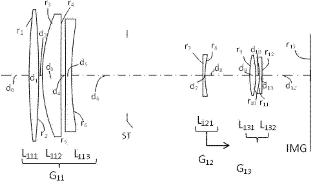
[0069] figure 1 It is a cross-sectional view along the optical axis showing the structure of the fixed-focus lens of Example 1. The fixed-focus lens is composed of the following lens groups arranged in order from the object side in the figure: the first lens group G11 with positive refractive power; the second lens group G12 with negative refractive power; The third lens group G13. In addition, an aperture stop ST defining a predetermined aperture is arranged between the first lens group G11 and the second lens group G12.

[0070] The first lens group G11 is configured such that a positive lens L111, a positive lens L112, and a negative lens L113 are arranged in this order from the object side. Also, the first lens group G11 is fixed and does not move during focusing.

[0071] As for the second lens group G12, it is composed of a negative lens L121. By moving the second lens group G12 along the optical axis from the object side to the imaging surface IMG side, focusing is ...

Embodiment 2

[0079] Figure 5 It is a cross-sectional view along the optical axis showing the structure of the fixed-focus lens of Example 2. The fixed-focus lens is composed of the following lens groups arranged in order from the object side in the figure: the first lens group G21 with positive refractive power; the second lens group G22 with negative refractive power; The third lens group G23. In addition, an aperture stop ST defining a predetermined aperture is arranged between the first lens group G21 and the second lens group G22.

[0080] The first lens group G21 is configured such that a positive lens L211, a positive lens L212, and a negative lens L213 are arranged in this order from the object side. Also, the first lens group G21 is fixed and does not move during focusing.

[0081] As for the second lens group G22, it is composed of a negative lens L221. By moving the second lens group G22 along the optical axis from the object side to the imaging surface IMG side, focusing is...

Embodiment 3

[0087] Figure 9 It is a cross-sectional view along the optical axis showing the structure of the fixed-focus lens of Example 3. The fixed-focus lens is composed of the following lens groups arranged in order from the object side in the figure: the first lens group G31 with positive refractive power; the second lens group G32 with negative refractive power; The third lens group G33. In addition, an aperture stop ST defining a predetermined aperture is disposed between the first lens group G31 and the second lens group G32.

[0088] The first lens group G31 is configured such that a positive lens L311, a positive lens L312, and a negative lens L313 are arranged in this order from the object side. Also, the first lens group G31 is fixed and does not move during focusing.

[0089] The second lens group G32 is composed of a negative lens L321. By moving the second lens group G32 along the optical axis from the object side to the imaging surface IMG side, focusing is performed ...


PUM


Abstract

The invention discloses a shortwave infrared telescope lens which is formed by the configuration of a first lens group with positive focal power, a second lens group with negative focal power and a third lens group with positive focal power from an object side orderly. The second lens group is formed by single lens elements. In the time of focusing, the second lens group moves along an optical axis, and the first lens group and the third lens group are fixed relative to an imaging surface. The invention provides the shortwave infrared telescope lens with a small size, light weight, large diameter, high resolution, excellent imaging performance and an inner focusing mode.

Description

technical field [0001] The invention relates to an infrared telescopic lens, in particular to an optical imaging lens suitable for short-wave infrared band (0.9-1.7 μm). Background technique [0002] Light in the short-wave infrared band (0.9-1.7 μm) cannot be directly observed by human eyes because it exceeds the spectral range of visible light, but its interaction with objects is the same as that of visible light. Compared with thermal imagers, which can only detect warm objects in a cold background, the images formed by the reflected light of short-wave infrared have shadows and contrasts, and the resolution and details of the images are comparable to those of visible light. In addition, since the illuminance emitted by the atmospheric phenomenon of sky radiance at night is almost all in the short-wave infrared band, the short-wave infrared imaging system can also clearly detect objects at night without moonlight. This kind of day and night imaging performance is not ava...

Claims


Application Information

Patent Timeline
Patent Type & Authority Applications(China)
IPC IPC(8): G02B13/02G02B13/14
CPCG02B13/02G02B13/14
Inventor 虞翔郑列华
Owner SHANGHAI INST OF TECHNICAL PHYSICS - CHINESE ACAD OF SCI
Why Eureka
Try Eureka