A multi-channel automatic test method and system for testing optical modules

An automatic test system and multi-channel technology, applied in the field of optical device module testing, can solve the problems of high labor costs and low production efficiency of optical module testing, and achieve good scalability and compatibility

Active Publication Date: 2017-06-09
GUANGXUN SCI & TECH WUHAN
View PDF6 Cites 0 Cited by
  • Summary
  • Abstract
  • Description
  • Claims
  • Application Information

AI Technical Summary

Problems solved by technology

[0004] In order to solve the above-mentioned problems of low production efficiency and high labor cost of optical module testing, the present invention provides a multi-channel-based optical module testing system and testing method. The testing system uses rack packaging instead of the tra

Method used


Image

  • A multi-channel automatic test method and system for testing optical modules
  • A multi-channel automatic test method and system for testing optical modules
  • A multi-channel automatic test method and system for testing optical modules

Examples


Example Embodiment

[0032] In order to make the objectives, technical solutions, and advantages of the present invention clearer, the present invention will be further described in detail below in conjunction with the embodiments and the drawings. Here, the exemplary embodiments of the present invention and the description thereof are used to explain the new implementation of the present invention, but not as a limitation to the present invention.

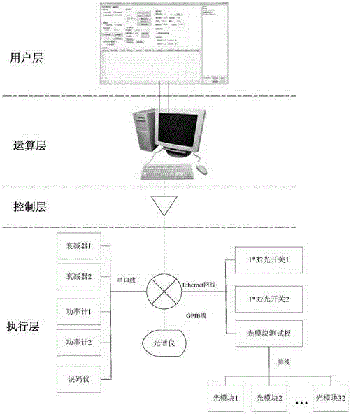
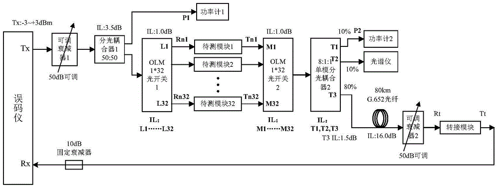
[0033] The optical path of the multi-channel automatic test system for optical modules provided by the present invention is as follows figure 1 As shown, it includes a code error meter, optical splitter 1, optical power meter 1, multiplex optical switch 1, multiple optical switch 2, split optical coupler 2, optical power meter 2, spectrometer, long-distance transmission fiber, and adapter module And the test control host (not shown in the figure); the multiple optical switch 1 is an input and N output optical switch, the multiple optical switch 2 is an N ...


PUM


Abstract

The invention relates to a multi-channel automatic test system used for testing optical modules and a method thereof. Multiple test optical channels are automatically switched by controlling selective conduction of multi-path optical switches arranged in pairs via a computer so that the optical modules to be tested in the multiple test optical channels are automatically tested in turn. Meanwhile, program control of optical power is realized via a variable optical attenuator, output optical power and the spectral characteristic are detected via an optical power meter and a spectrometer device, automatic control of the test system is realized via a test program and all the devices and instruments are installed in a machine frame so that a complete whole is finally formed. Optical module test efficiency and test accuracy can be enhanced by using the multi-channel automatic test system and the method thereof so that labor cost can be saved, and automatic and mass production of the product can be realized.

Description

technical field [0001] The invention relates to a method and a device for testing an optical device module, in particular to a method and a system capable of automatically testing an optical module with multiple channels. Background technique [0002] With the rapid development of optical communication technology, the demand for optical modules in optical communication systems is increasing. In the actual production and testing process of these optical modules, the usual practice is to manually insert an optical module into the test fixture, and then Perform the following test process: test the bit error of the optical module through a bit error meter, test the output spectrum of the optical module through a spectrometer, test the output optical power of the optical module through a power meter, etc. In the prior art, the bit error test is to test the bit error of the optical module by docking the bit error meter with the optical module. Test the bit error situation within ...

Claims


Application Information

Patent Timeline
IPC IPC(8): H04B10/073H04B10/079
Inventor 裴青峰李仲伟鲍婕喻杰奎周治柱
Owner GUANGXUN SCI & TECH WUHAN
Why Eureka
Try Eureka