Buffer units for elevators

A buffer unit and elevator technology, which is applied to elevators in buildings, lifting equipment in mines, elevators, etc., can solve the problems of expensive structure, heavy weight, large footprint, etc., and achieve the effect of small structure height

Inactive Publication Date: 2017-03-08
INVENTIO AG
View PDF8 Cites 0 Cited by
  • Summary
  • Abstract
  • Description
  • Claims
  • Application Information

AI Technical Summary

Problems solved by technology

In addition to the complex construction, this structure is also very expensive and bulky
Another disadvantage is that this structure requires a large footprint

Method used


Image

  • Buffer units for elevators
  • Buffer units for elevators
  • Buffer units for elevators

Examples


Embodiment Construction

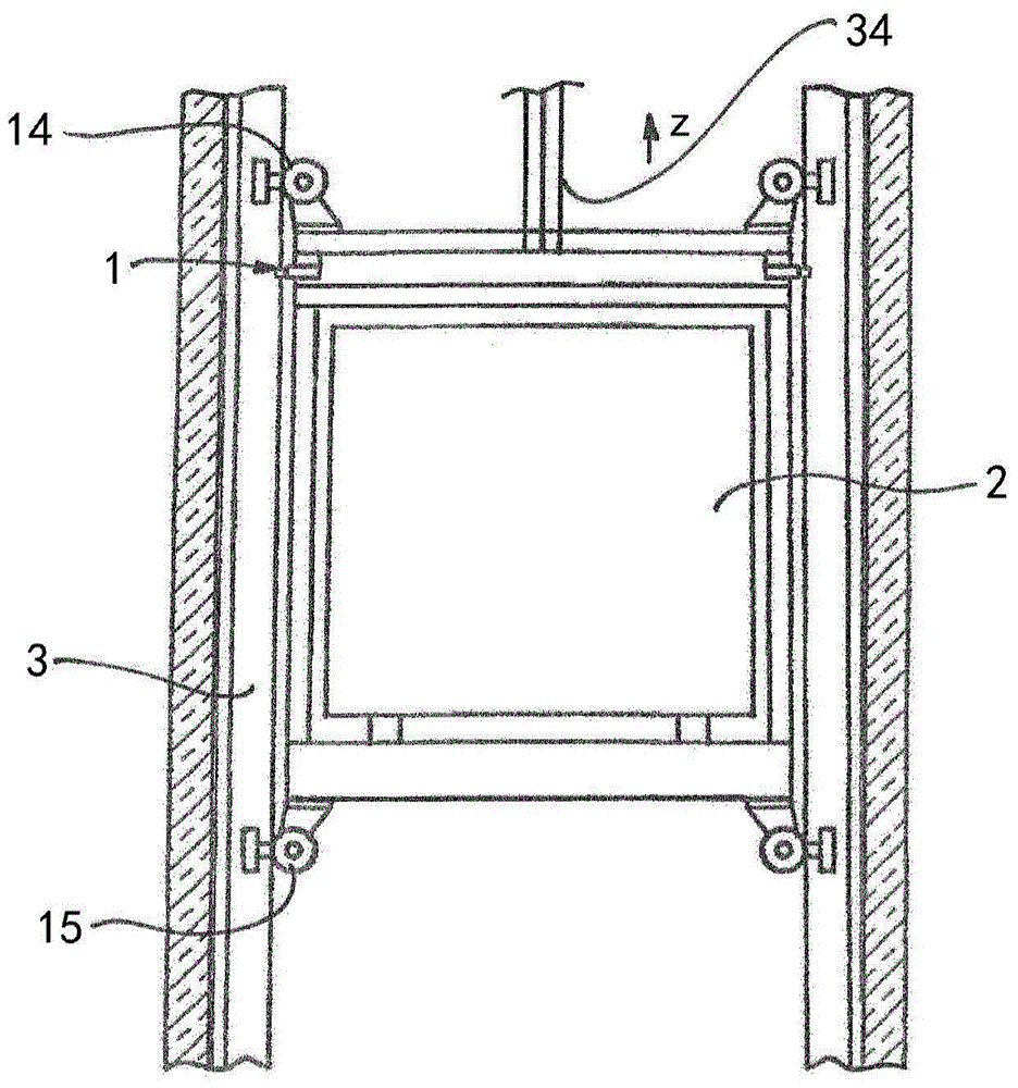
[0030] figure 1 An elevator with a car 2 for transporting people or goods that can move vertically up and down is shown. For example, a carrying mechanism 34 configured as a belt or a rope is used as the carrying mechanism for moving the car 2. In order to guide the car 2, the elevator installation has two guide rails 3 extending in the vertical running direction z. Here, each guide rail 3 has three guide surfaces extending in the traveling direction of the car. Installed on the car 2 figure 1 The guide shoe is configured as a roller guide shoe by way of example. With the buffer unit marked with 1, the undesired vertical vibration of the car can be reduced during parking. Such vertical vibration is generated when a person steps on or leaves the car 2. The car 2 is stuck in vibration due to the load change. This phenomenon is particularly evident in elevators with high shaft heights based on load-bearing belts. The direction in which the guide rail extends is indicated by z...


PUM


Abstract

A damping unit for an elevator to dampen vertical vibrations of a car (2) during parking has a brake jaw clamp (8, 8') with a brake jaw (7, 7') . The brake jaw clamps (8, 8') are connected with the shared electric motor (4) by means of a gear transmission mechanism. The gear train has a central drive gear (11) connected to the drive shaft (17) of the motor (4) and an eccentric for each brake jaw (7, 7') that is operatively connected to the drive gear (11). Gears (12, 12'). The brake jaws (7, 7') are elastically supported on the corresponding brake jaw clamps (8, 8') respectively by two helical pressure springs (5).

Description

Technical field [0001] The invention relates to a buffer unit for elevators. The elevator comprises a car which can be moved in the elevator shaft by means of a drive unit via a carrying mechanism, for example in the form of a carrying rope or a carrying belt. A guide rail is fixed in the elevator shaft, and the guide rail presets a linear guide for the elevator car. People or goods stepping into or leaving the elevator car during the parking period cause the car to generate undesirable vertical vibration due to the elasticity of the bearing mechanism. Such vertical vibrations appear especially in elevators that use load-bearing belts as the load-bearing mechanism, and such elevators have become more and more popular in the near future. Because the belt has a relatively unfavorable vibration performance compared to the steel cable, the vertical vibration has an adverse effect on the comfort and operational safety of passengers. Background technique [0002] From EP 1 067 084 B...

Claims


Application Information

Patent Timeline
Patent Type & Authority Patents(China)
IPC IPC(8): B66B5/18B66B17/34
CPCB66B5/18B66B17/34B66B1/365B66B11/0293
Inventor 洛伦茨·艾茨威勒汉斯·科赫尔
Owner INVENTIO AG
Why Eureka
Try Eureka