Tank for liquid-filled transformers or inductors

A technology of transformers and inductors, which is applied in the direction of transformer/inductor housing, transformer/inductor cooling, transformer/inductor components, etc., and can solve the problem that the sound insulation of transformers and inductors cannot be satisfactorily solved

Active Publication Date: 2015-02-04
西门子能源全球两合公司
View PDF9 Cites 3 Cited by
  • Summary
  • Abstract
  • Description
  • Claims
  • Application Information

AI Technical Summary

Problems solved by technology

[0009] The sound insulation of larger power transf...

Method used


Image

  • Tank for liquid-filled transformers or inductors
  • Tank for liquid-filled transformers or inductors
  • Tank for liquid-filled transformers or inductors

Examples


Embodiment Construction

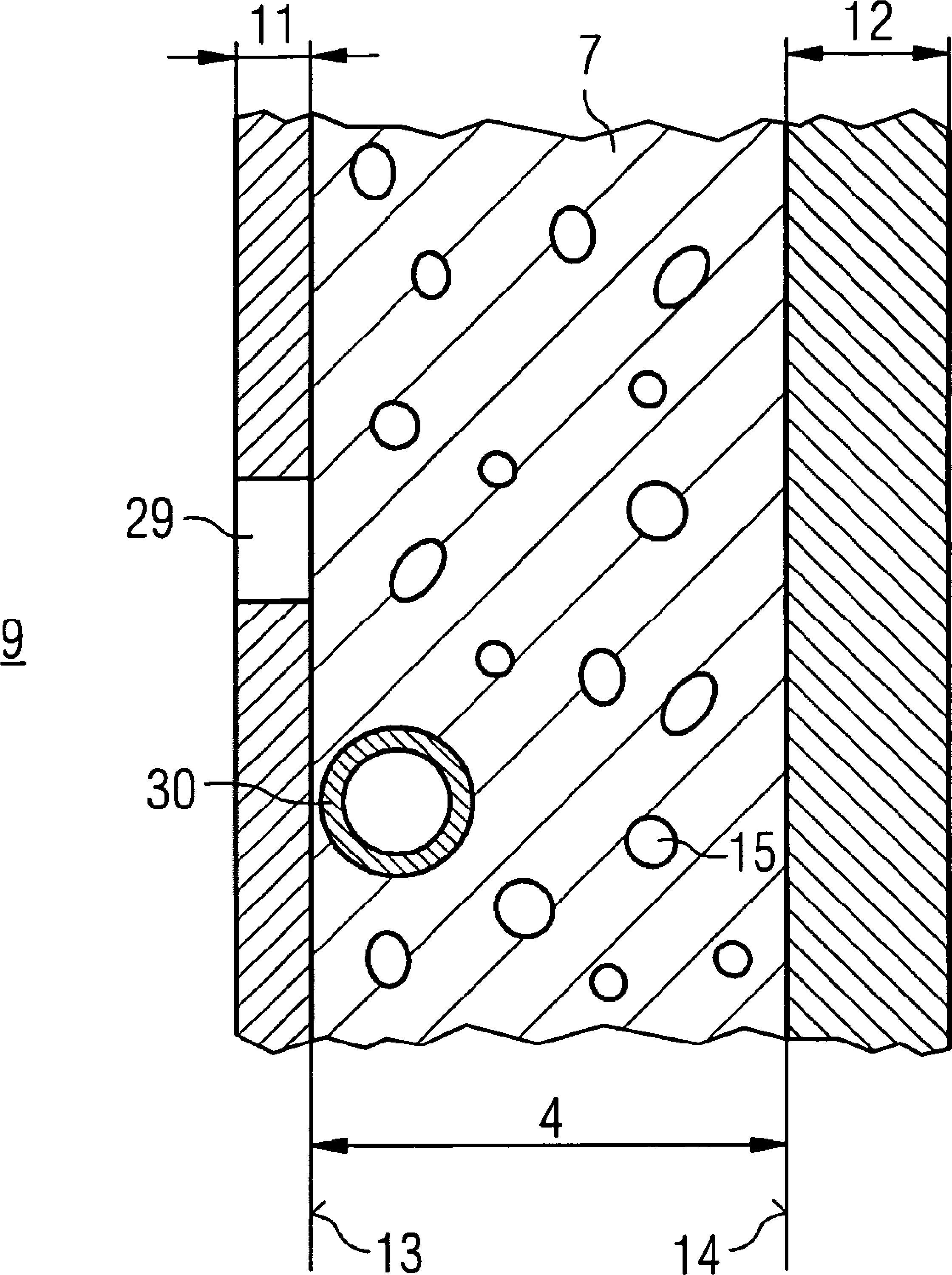
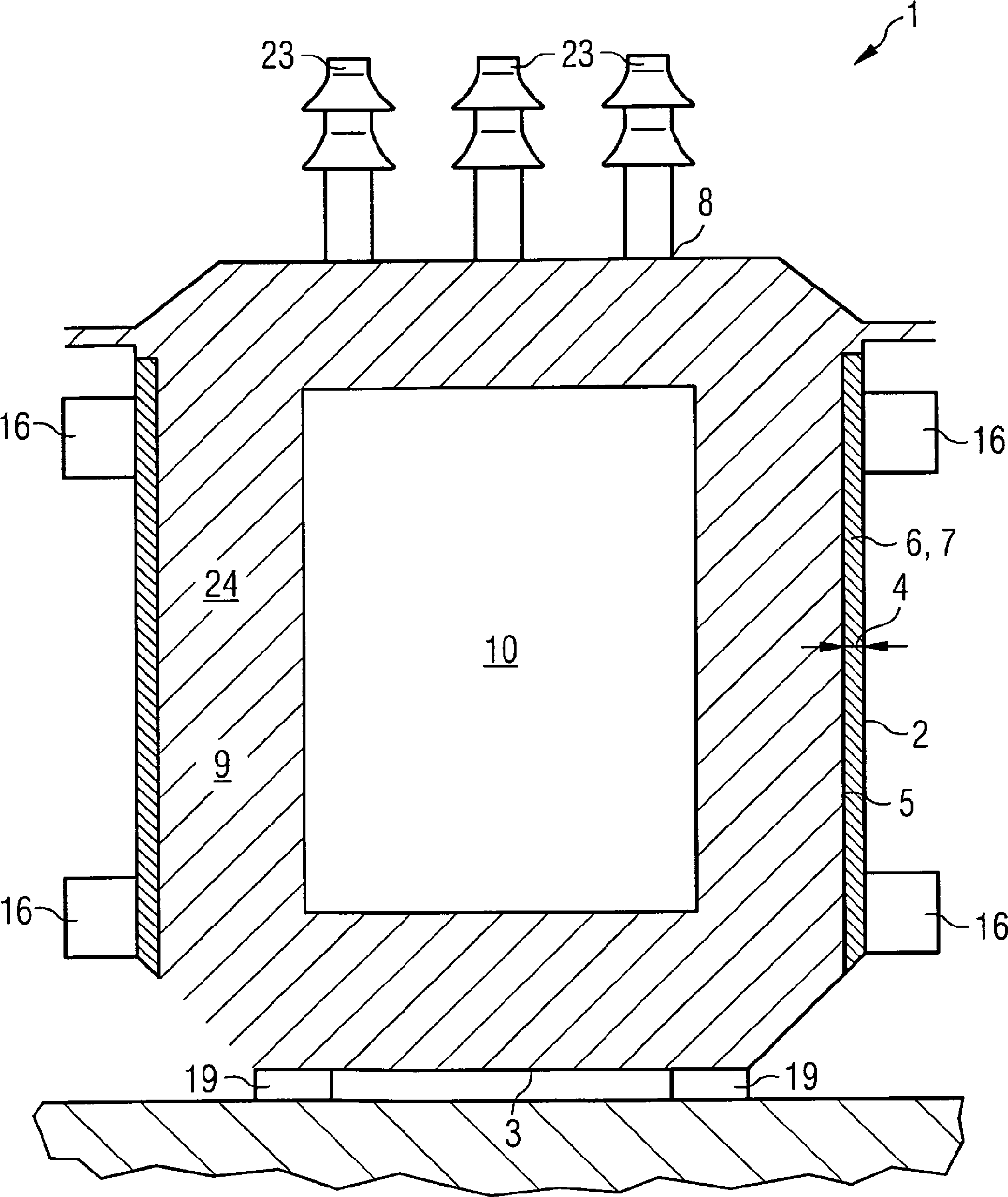
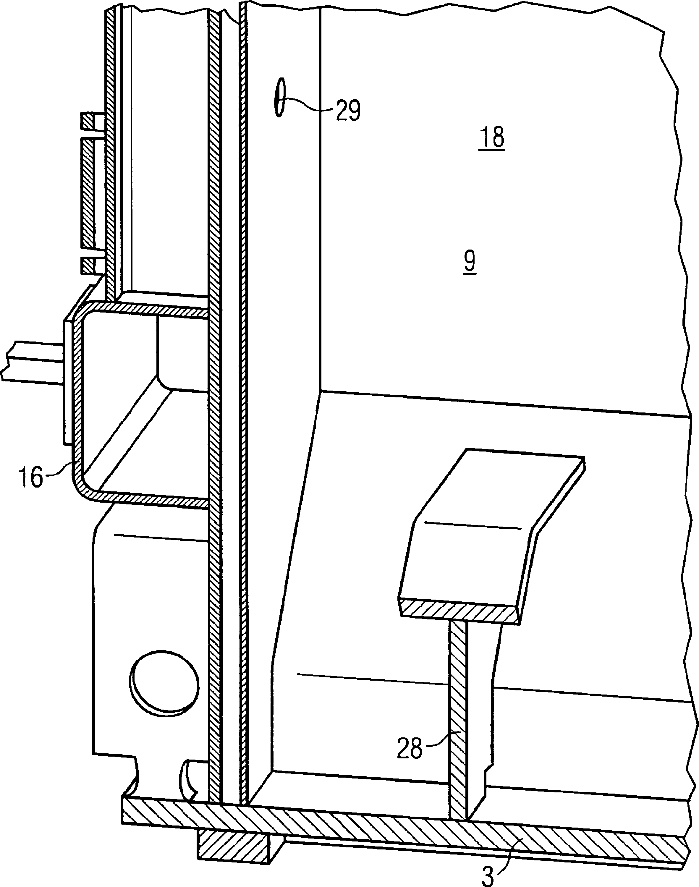
[0036] figure 1 Tank 1 is shown, the shell of which is designed in the manner of a double-wall tank. The two double walls 2 , 5 are formed by an outer tank shell 2 and an inner tank shell 5 , which are arranged at a distance 4 from one another. Between the two shells 2 , 5 there is a circumferential gap 6 which is filled according to the invention with a plastic or polymer material 7 . The outer shell 2 tapers downwards to a bottom surface portion 3 . The bottom part 3 is supported on elastic supports 19 on a base. An electrical connection 23 (Durchführungen (penetration)) is arranged on the cover 8 . Before the transformer / inductor is put into operation, a negative pressure is normally generated in the inner chamber 9 . In order to ensure the mechanical stability of the tank under vacuum, different reinforcements are installed on the tank in the interior as well as in the field, among which, the figure 1 For the sake of overview, only the reinforcements 16 arranged in th...


PUM


Abstract

Tank for a liquid-filled transformer or inductor, comprising: a) an outer tank casing (2) comprising a bottom part (3); b) an inner tank casing (5), enclosed by the outer tank casing (2) at a distance (4), wherein the outer tank casing (2) and the inner tank casing (5) are formed from metal; c) a plastic or polymer material (7), which is incorporated in an intermediate space (6), bounded by the inner surface (14) of the outer tank casing (2) and the inner surface (13) of the inner tank casing (5), and at least partially fills this intermediate space (6), wherein the plastic or polymer material and the adhesion thereof to the inner surfaces (13, 14) is designed such that d) shearing forces are transmitted between the inner and outer tank casings (2, 5) and that e) the transmission of structure-borne sound that is generated in the case of operation of an active part (10) arranged in the interior space (9) of the tank between the inner tank casing (5) and the outer tank casing (2) is inhibited.

Description

technical field [0001] The invention relates to a tank for a liquid-filled transformer or inductor, as used in an energy supply network. Background technique [0002] Electrical transformers or inductors used in energy supply networks usually consist of a magnetic core with electrical windings contained in a tank filled with an insulating and cooling liquid, such as oil. [0003] The disadvantage is that during operation of the transformer or inductor, the magnetic core causes the surrounding insulating and cooling liquid to vibrate by magnetostriction and also the force acting on the individual conductors of the winding. These vibrations propagate into the insulating and cooling liquid and excite the tank walls to produce unwanted sound radiation. [0004] In order to reduce the operating noise of transformers or inductors, passively acting measures have been known for a long time. [0005] From DE 23 09 564 it is known, for example, that the outer wall of the transformer...

Claims


Application Information

Patent Timeline
IPC IPC(8): H01F27/02H01F27/12H01F27/33
CPCH01F27/12H01F27/025H01F27/33H01F27/10
Inventor F.阿梅茨伯格A.霍泽尔H.弗雷加特纳H.雷奇伯格H.肖伯
Owner 西门子能源全球两合公司
Why Eureka
Try Eureka