System for attaching film

A technology of film sticking and film sticking, which is applied in the direction of lamination auxiliary operations, instruments, chemical instruments and methods, etc., and can solve problems such as difficult management of polarizing films, backflush errors, errors, etc.

Active Publication Date: 2015-02-11
LG ELECTRONICS INC
View PDF4 Cites 5 Cited by
  • Summary
  • Abstract
  • Description
  • Claims
  • Application Information

AI Technical Summary

Problems solved by technology

[0007] In the prior art, the polarizing film is cut according to the size of the display panel, that is, the sheet-to-panel scheme, and then the cut polarizing film should be attached independently, so it has the following disadvantages: Processing costs due to film cutting, thus increasing manufacturing costs
[0008] In addition, there is a disadvantage that after film cutting, it is difficult to manage the cut polarizing film due to deformation caused by the storage environment
In this prior art (i.e. said roller-to-panel solution), the panel and the film travel in the same direction, so there is the disadvantage that the attachment position of the film supplied by the roller is not the same as the attachment position of the panel glass to be advanced. repeatable alignment
[0010] This results in a phenomenon that allows the film to sag when it is unwound from the film roll, and thus has the following disadvantages: no Precisely control where the membrane is attached
[0011] In general, the attachment accuracy of the film is ±0.1 mm from the edge of the panel glass, where there is a disadvantage that due to the backflushing of the drive conveyor and the The error caused by the elongation of the film, the attachment accuracy is reduced compared with the existing technology

Method used


Image

  • System for attaching film
  • System for attaching film
  • System for attaching film

Examples


Embodiment Construction

[0030] Hereinafter, embodiments of the present invention will be described in detail with reference to the accompanying drawings.

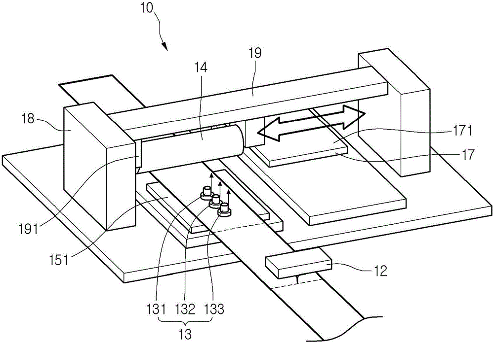
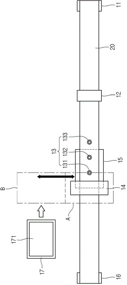
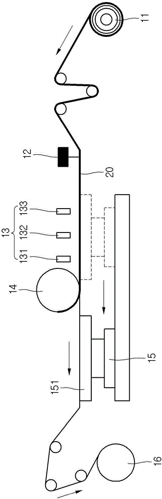
[0031] figure 1 is a perspective view of a system for sticking films according to one embodiment of the present invention, figure 2 is a top view of the system for film application, image 3 is a side view of the system for film application.

[0032] refer to Figure 1 to Figure 3 , the system 10 for sticking film according to the embodiment of the present invention comprises: supply roller 11, and this supply roller 11 is wound with polarizing film 20, and this polarizing film 20 is provided with polarizer or pattern retarder; Part cutter 12, part cutter 12 Cut the polarizing film 20 unwound from the supply roller 11 in a direction perpendicular to the traveling direction of the film based on the size of the panel, and completely cut off the part except the release film placed on the bottom plate; camera module 13, the camera module 13 recog...


PUM


Abstract

A system for attaching film comprises a feeding roller, a cutter, a film carrier, an attaching roller, a recycling roller, a panel carrier and a panel. The feeding roller is wound by a film component which is formed in way that a polarizing film or 3D polarizing film, an adhesive film and a stripping film are stacked in order. The cutter cuts off the polarizing film or 3D polarizing film and the adhesive film of the film component, except the stripping film, being supplied by the feeding roller completely. The film carrier guides the film component which is partly cut off to a film separation region. The attaching roller is placed on the film separation region, and adsorbs the film part which is cut off by the cutter and comprises the polarizing film or 3D polarizing film and the adhesive film. The recycling roller is wound on the stripping film which goes over the attaching roller. The panel carrier is moved to a film attaching area which is spaced from the film separation region. Under the condition of being arranged on the panel carrier, the panel is moved to the film attaching area, after the attaching roller adsorbs the film part in the film separation region, the attaching roller is moved to the film attaching area, when the panel passes through the film attaching area, the film part adsorbed on the attaching roller is attached to the top surface of the panel.

Description

technical field [0001] The invention relates to a system for applying films. Background technique [0002] The present invention relates to a system for attaching polarizing films to panels in the manufacture of LCD modules. Existing polarizing film attachment schemes include sheet to panel scheme and roll to panel scheme. [0003] The sheet-to-panel solution supplies and applies sheets cut to the panel size, and the roll-to-panel solution applies film supplied in the state of a fabric roll to the panel. [0004] In recent years, in order to watch a video output from an LCD module as a stereoscopic image, many kinds of stereoscopic image display devices, such as 3D TVs equipped with a panel to which a polarizing film is attached, have appeared. [0005] Stereoscopic image display devices use stereoscopic technology or autostereoscopic technology. In recent years, with the commercialization of stereoscopic image display devices and the development of various technologies, ...

Claims


Application Information

Patent Timeline
Patent Type & Authority Applications(China)
IPC IPC(8): B32B37/00B32B38/00B32B38/18B32B41/00
CPCB32B37/0053B32B38/04B32B38/10B32B41/00B32B37/0046G02F1/1303G02F1/1335
Inventor 曹在俊任玉均姜昌佑郑再植
Owner LG ELECTRONICS INC
Why Eureka
Try Eureka