Supercharge Your Innovation With Domain-Expert AI Agents!

Belt protection mechanism for automatic tensioning area of ​​belt conveyor

A technology for belt conveyors and protection mechanisms, applied in the direction of conveyors, conveyor objects, conveyor control devices, etc., can solve the problem of severe contact between the conveyor belt and the steel structure of the tension platform, damage to the rubber-covered structure of the roller, and problems between the roller and the belt. Injuries and other problems can be avoided, and the effect of avoiding stacking or even tearing and prolonging the service life

Active Publication Date: 2016-08-10
MCC BAOSTEEL TECH SERVICE
View PDF5 Cites 0 Cited by
  • Summary
  • Abstract
  • Description
  • Claims
  • Application Information

AI Technical Summary

Problems solved by technology

[0003] 1) Belt trimming due to deviation
[0004] When the running conveyor belt deviates, the deflected belt easily rubs violently with the steel structure of the tensioning part, causing the belt to trim
(Because of the deviation detection limit, when the belt reruns, the operator needs to remove the detection limit before the conveyor belt can be dynamically adjusted. Frequent disassembly and assembly cause errors in the installation position and angle accuracy of the detection limit, which affects the protection of the conveyor belt. )
[0005] 2) The spilled material caused by deviation will accumulate in the tension part and cause damage to the roller and belt
During the operation of the conveyor belt, the material will be spilled due to deviation, and the falling mineral material will fall directly on the non-working surface of the conveyor belt in the tensioning part, and then be sandwiched between the roller and the belt. The mineral material between the conveyor belt and the high-tension reciprocating circular motion not only causes serious damage to the rubber lagging structure of the pulley, but also increases the amount of mineral material sandwiched between the pulley and the conveyor belt, eventually causing the center of the belt to bulge , when the raised part passes the roller, it will cause the center of the conveyor belt to overlap. As the falling mineral material continues to increase, the height of the conveyor belt is also increased (that is, the distance between the conveyor belt and the roller increases) , due to the compact structure of the tensioning part, the conveyor belt will eventually come into severe contact with the steel structure of the tensioning platform until the conveyor belt is torn
Such equipment accidents have occurred many times on belt conveyors, which not only caused production interruptions, but also required a lot of time, manpower and expenses to recover, which brought additional cost burdens to business operations
[0007] 3) The belt is stacked, and due to the increase in thickness, it rubs against the steel structure of the tensioning trolley, causing tearing
[0008] The working surface of the conveyor belt is stained with mineral materials and runs with the belt. Due to vibration on the return surface of the belt, the adhesive mineral materials fall between the tensioning roller and the belt, and the relative position of the rollers remains unchanged. The belts run overlappingly on the drum, causing the folded belts to rub against the steel structure of the tensioning trolley, causing the conveyor belt to tear

Method used


Image

  • Belt protection mechanism for automatic tensioning area of ​​belt conveyor
  • Belt protection mechanism for automatic tensioning area of ​​belt conveyor

Examples


Embodiment Construction

[0035] The implementation of the present invention will be illustrated by specific specific examples below, and those skilled in the art can easily understand other advantages and effects of the present invention from the contents disclosed in this specification.

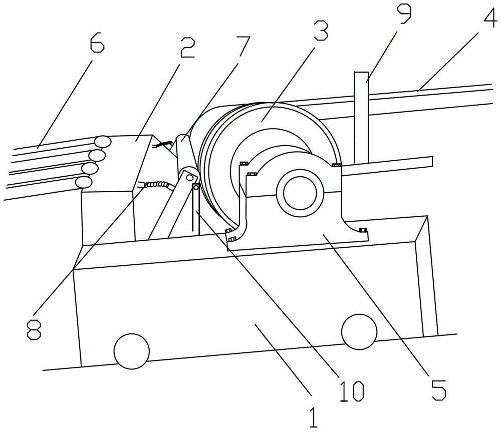
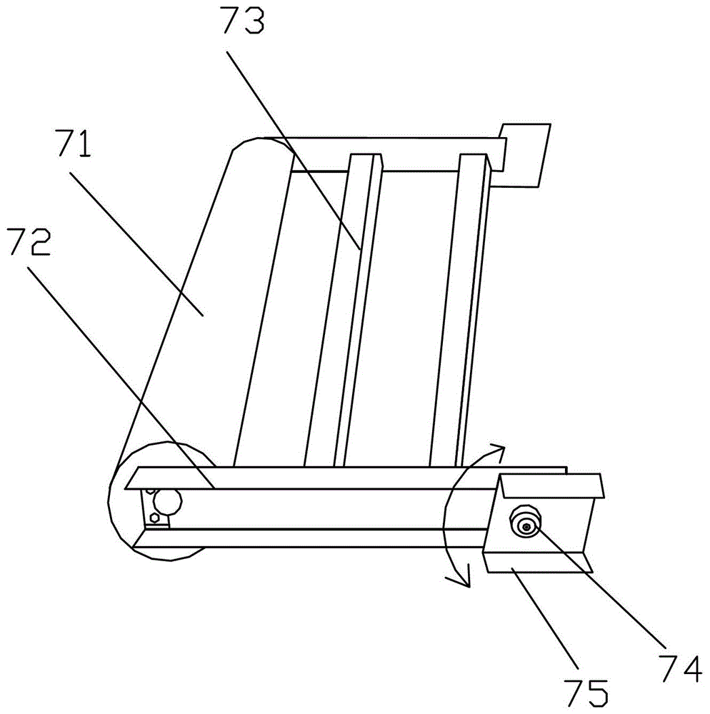
[0036] see figure 1 , 2 . It should be noted that the structures, proportions, sizes, etc. shown in the drawings attached to this specification are only used to match the content disclosed in the specification, for those who are familiar with this technology to understand and read, and are not used to limit the implementation of the present invention. Limiting conditions, so there is no technical substantive meaning, any modification of structure, change of proportional relationship or adjustment of size, without affecting the effect and purpose of the present invention, should still fall within the scope of the present invention. The disclosed technical content must be within the scope covered. At the same time,...


PUM


Abstract

The invention provides an automatic tensioning area belt protection mechanism of a belt conveyor. The automatic tensioning area belt protection mechanism comprises a tensioning platform, a tensioning roller and a tensioning trolley, wherein an anti-coiling device is arranged between the tensioning platform and the tensioning roller and comprises a transverse carrier roller; two carrier roller brackets are respectively arranged at the two ends of the transverse carrier roller, and are articulated with the tensioning trolley. When the scattered material drops onto a returning belt of the tensioning part as the upper part of the conveyor belt is off tracking, the scattered mineral aggregate is accumulated between the tensioning roller and the conveyor belt to enlarge the contact distance between the working surface of the conveyor belt and the tensioning roller, at the moment the conveyor belt detached from the tensioning roller is in contact with the transverse carrier roller of the anti-coiling device, the carrier roller brackets of the anti-coiling device are detached from an induction detector, the induction detector generates feedback signals to a control system of the belt conveyor, so as to enable the conveyor belt to stop working. Therefore, the automatic tensioning area belt protection mechanism can avoid the phenomenon that the conveyor belt in the tensioning area of the belt conveyor is coiled, and even torn up, and then the service life of the conveyor belt can be prolonged.

Description

technical field [0001] The invention relates to a belt conveyor, in particular to a device for protecting the belt in the automatic tensioning area of ​​the belt conveyor. Background technique [0002] At present, the deviation safety protection measures for the running of the belt conveyor belt can only be protected by the deviation detection limit. There are two ways to protect the conveyor belt by the deviation detection limit (light running and heavy running). When the deviation occurs, the detection limit will transmit the signal to the operator through the central control to correct the deviation of the conveyor belt in time. Since the belt conveyor is mainly used to transport bulk cargo (coal, ore), due to reasons such as the working environment, operators and different properties of the mineral material, it is inevitable that the material will be scattered due to deviation during the process of conveying the mineral material. Phenomenon, the part of the spilled mine...

Claims


Application Information

Patent Timeline
Patent Type & Authority Patents(China)
IPC IPC(8): B65G43/02
CPCB65G43/02B65G2203/042
Inventor 黄庆祥陈雪明黄水平周安叶
Owner MCC BAOSTEEL TECH SERVICE
Features
  • R&D
  • Intellectual Property
  • Life Sciences
  • Materials
  • Tech Scout
  • Unparalleled Data Quality
  • Higher Quality Content
  • 60% Fewer Hallucinations
Learn More