Clamping turning device

A turning device and clamping technology, which is applied in the direction of transportation and packaging, conveyor objects, etc., can solve the problems of complex structure and large space occupation, and achieve the effect of simple operation, convenient clamping and simple structural design

Active Publication Date: 2015-02-11
SUZHOU MEISHANZI GARMENTS CO LTD
View PDF9 Cites 11 Cited by
  • Summary
  • Abstract
  • Description
  • Claims
  • Application Information

AI Technical Summary

Problems solved by technology

However, the existing clamping and turning device has the defects of complex structure and large spa

Method used


Image

  • Clamping turning device
  • Clamping turning device

Examples


Embodiment Construction

[0019] Preferred embodiments of the present invention will be described in detail below in conjunction with the accompanying drawings.

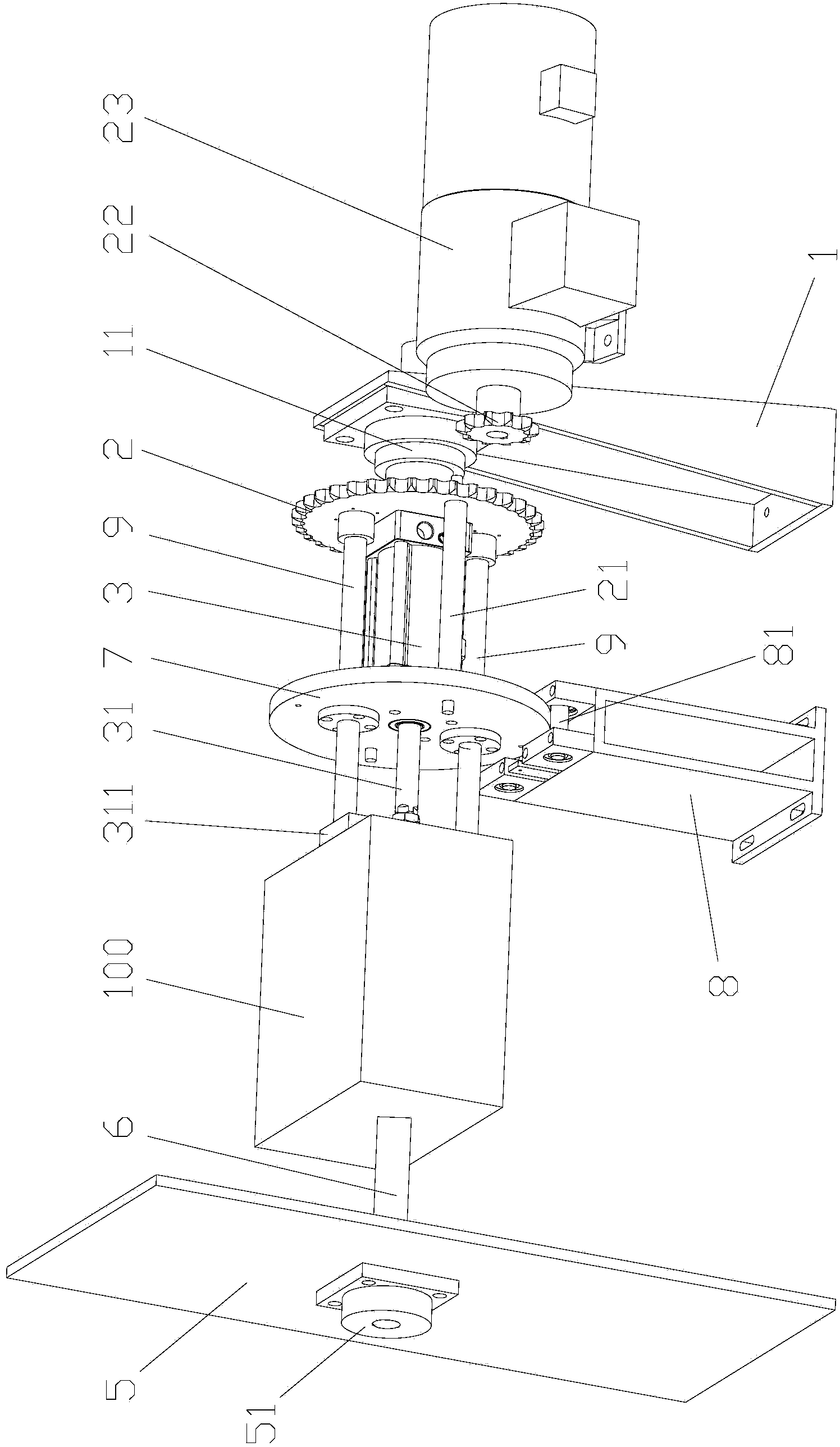
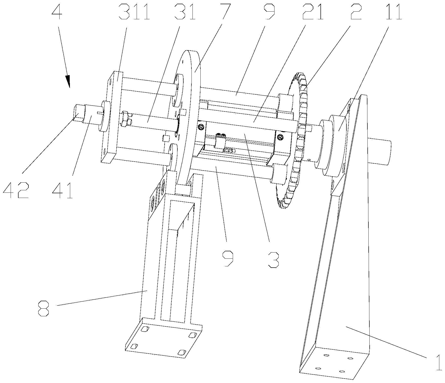
[0020] like figure 1 and figure 2 As shown, a clamping and turning device includes an active clamping and turning structure and a driven clamping and turning structure arranged opposite to each other at intervals. The active clamping and turning structure includes a rotating bracket 1, a turning wheel 2 rotatably mounted on the turning bracket 1, a clamping cylinder 3 fixedly arranged on the turning wheel 2 and rotating with the turning wheel 2, and the clamping cylinder 3 has a telescopic piston rod 31. The front end of the piston rod 31 is provided with an active clamping part 4 that is ejected and retracted with the piston rod 31 . The rotating support 1 has a rotating bearing 11, and the turning wheel 2 is connected to the rotating bearing 11.

[0021] The driven clamping and turning structure includes a fixed side plate 5, a driven c...


PUM


Abstract

The invention provides a clamping turning device which comprises an active clamping turning structure, a passive clamping turning structure as well as a driving mechanism, wherein the active clamping turning structure and the passive clamping turning structure are arranged at an interval oppositely; the active clamping turning structure comprises a rotating bracket, a turning wheel which is rotationally mounted on the rotating bracket, and a clamping cylinder which is fixedly arranged on the turning wheel and rotates along with the turning wheel; the clamping cylinder is provided with a telescopic piston rod; an active clamping part which is ejected out and retracted along with the piston rod is arranged at the front end of the piston rod; the passive clamping turning structure comprises a fixed side plate and a passive clamping part which is rotationally connected with the fixed side plate; the clamping cylinder is arranged between the fixed side plate and the turning wheel; the piston rod ejects out towards the passive clamping part; a space for clamping and turning a workpiece is formed between the passive clamping part and the active clamping part; the driving mechanism is used for driving the turning wheel to rotate. Compared with the prior art, the clamping turning device is compact in structure, simple and concise in design, convenient to mount, and applicable to mounting in a relatively small space.

Description

technical field [0001] The invention relates to a clamping and turning device which can not only clamp an object, but also turn the object over. Background technique [0002] In the production process, it is often encountered that the workpiece, fixture or mold must be clamped in a specific space and then turned over. A clamping and turning device is needed to clamp the thermocompression mold through the clamping part, and then turn the thermocompression mold 180° through the overturning part. However, due to the relatively independent structure of the clamping part and the turning part, the existing clamping and turning device has the defects of complex structure and large space occupation. Contents of the invention [0003] In order to overcome the above-mentioned defects of the prior art, the purpose of the present invention is to provide a clamping and turning device with simple design, compact structure and reduced space occupation. [0004] To achieve the above obj...

Claims


Application Information

Patent Timeline
IPC IPC(8): B65G47/248
Inventor 商利兵
Owner SUZHOU MEISHANZI GARMENTS CO LTD
Why Eureka
Try Eureka