
Partition and construction method thereof

A construction method and space interval technology, applied in the direction of walls, building components, covering/lining, etc., can solve the problems of difficult construction, easy damage, and difficult construction, and achieve the effect of convenient assembly and construction

Inactive Publication Date: 2015-02-11
郭恒盛 +1
View PDF6 Cites 3 Cited by
  • Summary
  • Abstract
  • Description
  • Claims
  • Application Information

AI Technical Summary

Problems solved by technology

[0004] However, it is known that during the construction of hydropower projects, due to the configuration of the hydropower pipelines, the two opposite surfaces of the sound insulation materials will communicate with each other, resulting in poor sound insulation effects
[0005] Furthermore, the conventional knowledge also has the problem of difficult construction: (1) When installing sound insulation materials, due to the need to lock them with a considerable number of screw lock components, the lack of construction is quite troublesome; (2) In the process of During the configuration of water and electricity pipelines, secondary processing operations were carried out due to the need to destroy the sound insulation materials, resulting in one more construction. In addition to prolonging the working hours, it also highlighted the problem that conventional construction is not easy
[0006] In addition, it is known that the two ends of the horizontal bar protrude beyond the outermost two vertical frames through the perforation, so that the builder must cut it off again, which is obviously troublesome and inconvenient; and the builder cannot make the horizontal bar Both ends are suspended in the air, because in this way, the outermost stand will not be connected with any crossbar, resulting in weak structural strength and easy damage

Method used


Image

  • Partition and construction method thereof
  • Partition and construction method thereof
  • Partition and construction method thereof

Examples


Embodiment Construction

[0080] In order to further understand the features, features and technical content of the present invention, please refer to the following detailed description and accompanying drawings of the present invention, but the accompanying drawings are provided for reference and illustration only, and are not intended to limit the present invention.

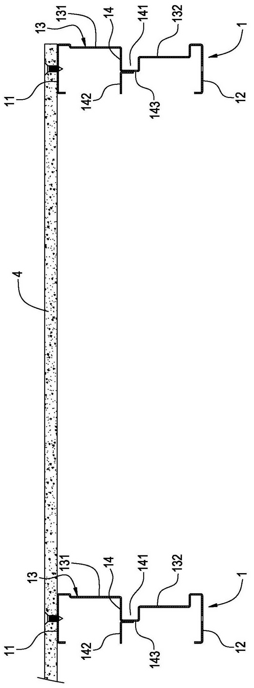
[0081] The invention provides a partition wall and its construction method, such as Figure 7 , Figure 8 The perspective view and top view schematic diagram of the partition wall of the present invention are shown as partition walls, ceilings or floor slabs applied to the interior of the building, or applied to the exterior walls of the building. The present invention is not limited, and the partition wall will be used below wall as an example.

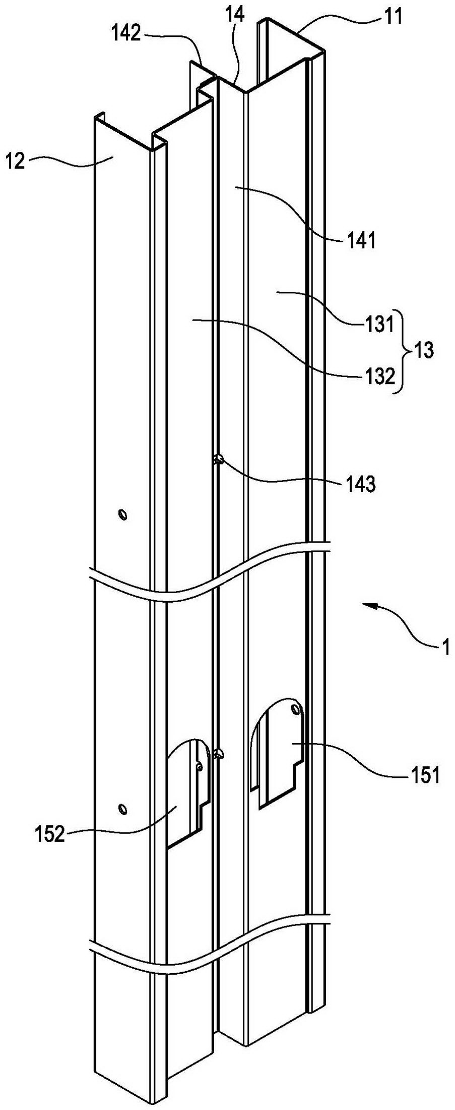
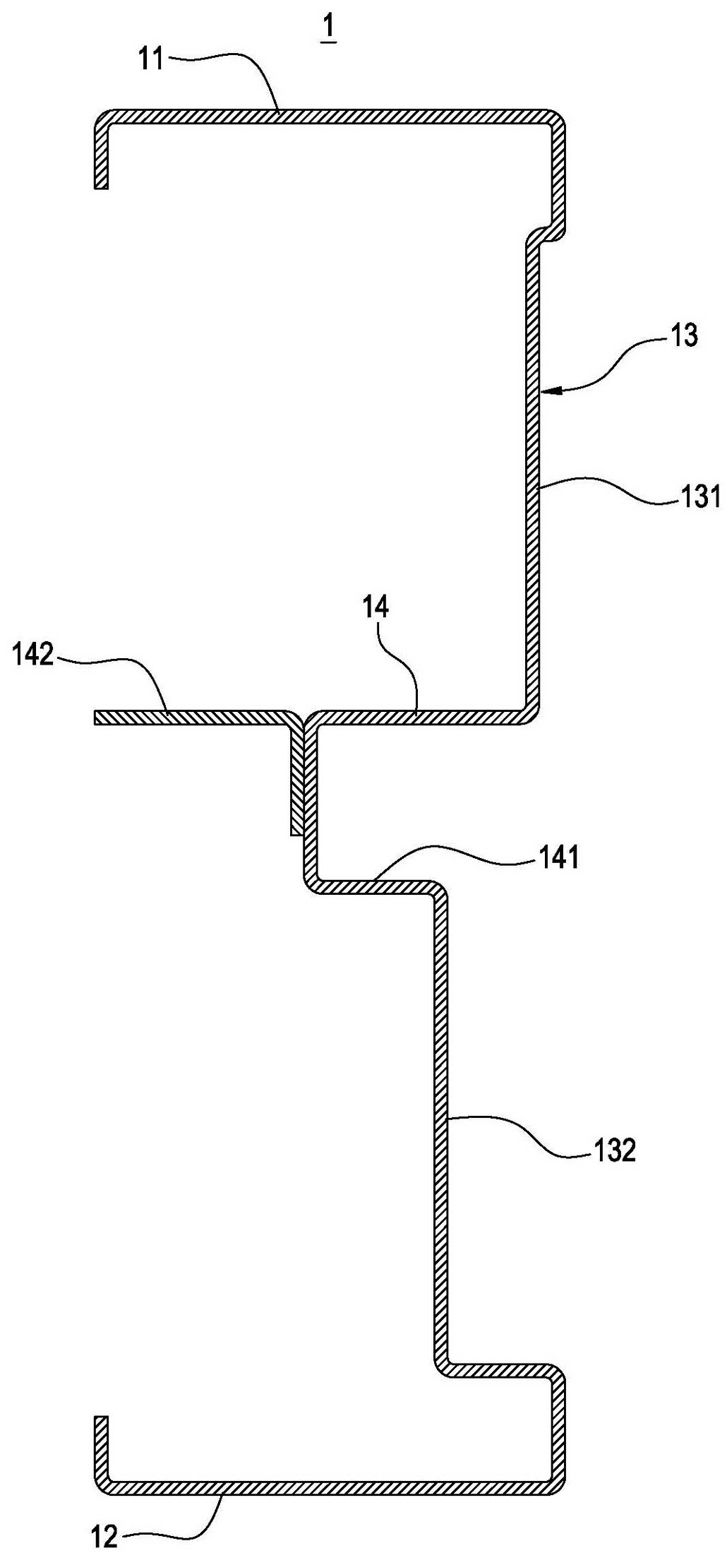
[0082] Such as Figure 1~Figure 8 The first embodiment of the partition wall of the present invention shown includes: a plurality of vertical frames 1, a plurality of inner panels 3 and two ...


PUM


Abstract

A partition includes at least two stands (1) spaced apart from each other, wherein each of the stands (1) includes a first panel (11), a second panel (12) corresponding to the first panel (11) and a lateral plate (13) connecting the first panel (11) and the second panel (12); at least one inner plate (3), wherein two sides of the inner plate (3) are respectively fixed to and between the two stands (1); and two outer plates (4, 5) respectively fixed to and between the first panel (11) of each stand (1) and the second panel (12) of each stand (1), wherein the two outer plates (4, 5) and the inner plate (3) form two spaces (6, 7) respectively. The inner plate 3 separates the two spaces (6, 7), so the partition is capable of performing better sound insulation effects and is more convenient to be assembled.

Description

technical field [0001] The invention relates to a partition wall, in particular to a partition wall applied to buildings and a construction method thereof. Background technique [0002] With regard to partition walls, such as partition walls, ceilings or floors inside a building, or exterior walls outside a building, etc., all belong to partition walls, and the partition walls will be used as an example to illustrate below. [0003] It is known that during construction, corresponding sky rails and ground rails are first installed on the ceiling and floor, and then a plurality of U-shaped stands are erected between the sky rails and the ground rails, and then sealed on one side of these stands The first outer panel, and after the construction of the hydropower project is completed, the sound insulation material is arranged between the sky rail, the ground rail, the stand and the first outer panel, and finally the second outer panel is sealed on the other side of these stands....

Claims


Application Information

Patent Timeline
IPC IPC(8): E04B2/74E04B2/82
CPCE04B2/44E04F13/0869E04B2/54E04C2/52E04C2/34E04F13/0803E04F13/0866E04C2002/3488E04C2/46E04C2/521
Inventor 郭恒盛郭宥锋
Owner 郭恒盛
Learn More