

Stepless speed change clutch for dune buggy
A continuously variable transmission and clutch technology, applied in clutches, automatic clutches, portable lifting devices, etc., can solve the problems of transmission belt friction and wear, poor speed change stability, easy wear of rollers, etc., and achieve small contact friction resistance, smooth speed change, and movement resistance small effect
- Summary
- Abstract
- Description
- Claims
- Application Information
AI Technical Summary
Problems solved by technology
Method used
Image

Examples
Embodiment Construction
[0029] The present invention will be further described below in conjunction with the accompanying drawings and embodiments.
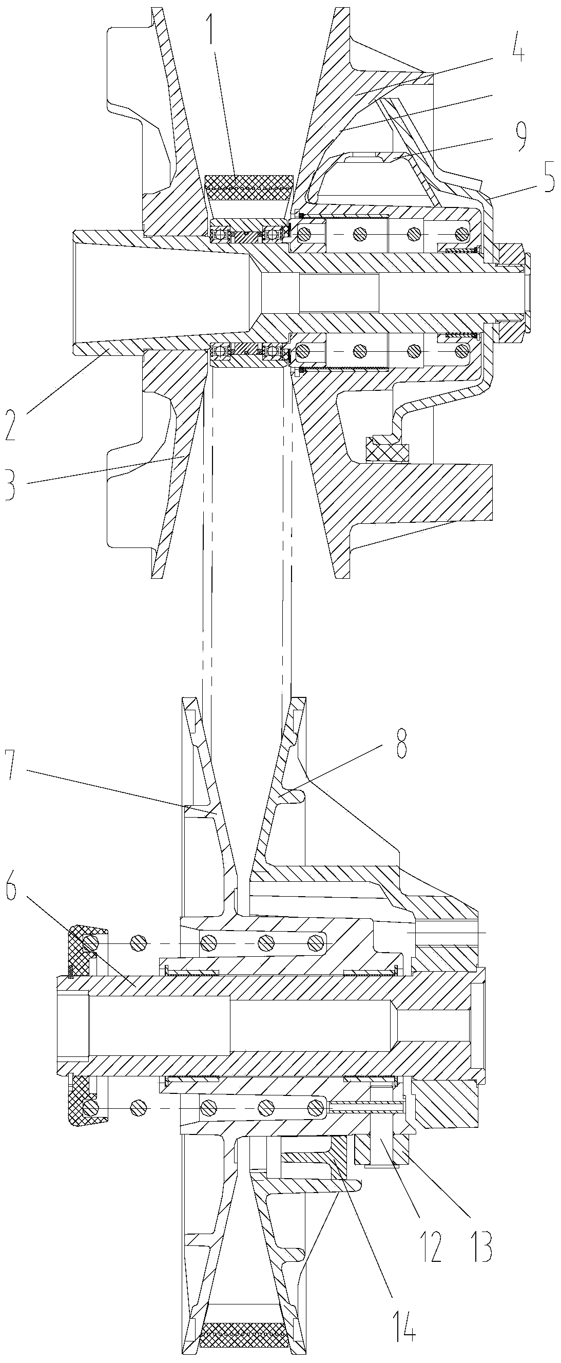
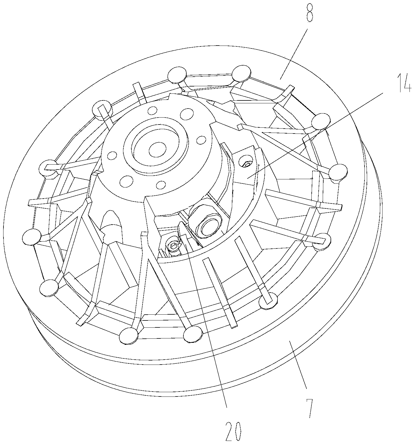
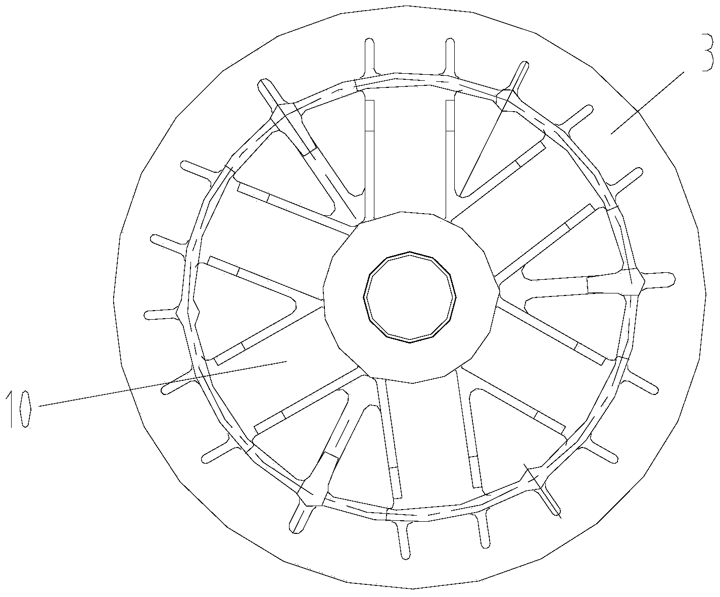
[0030] As shown in the figure, the continuously variable clutch of the ATV in this embodiment includes a driving wheel combination, a transmission belt 1 and a driven wheel combination. The driving wheel combination includes a driving shaft 2, a driving disc 3 fixed on the driving shaft, and a driving The moving wheel 4 on the shaft and slidingly matched with the driving shaft, and the slope plate 5 fixed on the driving shaft; the driven wheel combination includes a driven shaft 6, a fixed plate 7 fixed on the driven A moving disc 8 on the shaft and slidingly matched with the driven shaft, and a guide device;
[0031] A slide block 9 is arranged between the moving wheel and the ramp plate, a guide groove 10 for positioning the slider is provided on the moving wheel, the bottom of the guide groove is an arc-shaped curved surface, and the slide block cont...
PUM
 Abstract
Description
Claims
Application Information