Spiral guiding stepless variable transmission

A continuously variable speed change, clutch technology, applied in belts/chains/gears, mechanical equipment, transmission devices, etc., can solve the problems of poor starting stability, friction and wear of transmission belts, etc. Effect

Inactive Publication Date: 2015-02-11
CHONGQING CHANGXING IND
View PDF5 Cites 5 Cited by
  • Summary
  • Abstract
  • Description
  • Claims
  • Application Information

AI Technical Summary

Problems solved by technology

[0006] In view of this, the object of the present invention is to provide a helical guide continuously variable clutch to solve the problems of

Method used


Image

  • Spiral guiding stepless variable transmission
  • Spiral guiding stepless variable transmission
  • Spiral guiding stepless variable transmission

Examples


Embodiment Construction

[0022] The present invention will be further described below in conjunction with the accompanying drawings and embodiments.

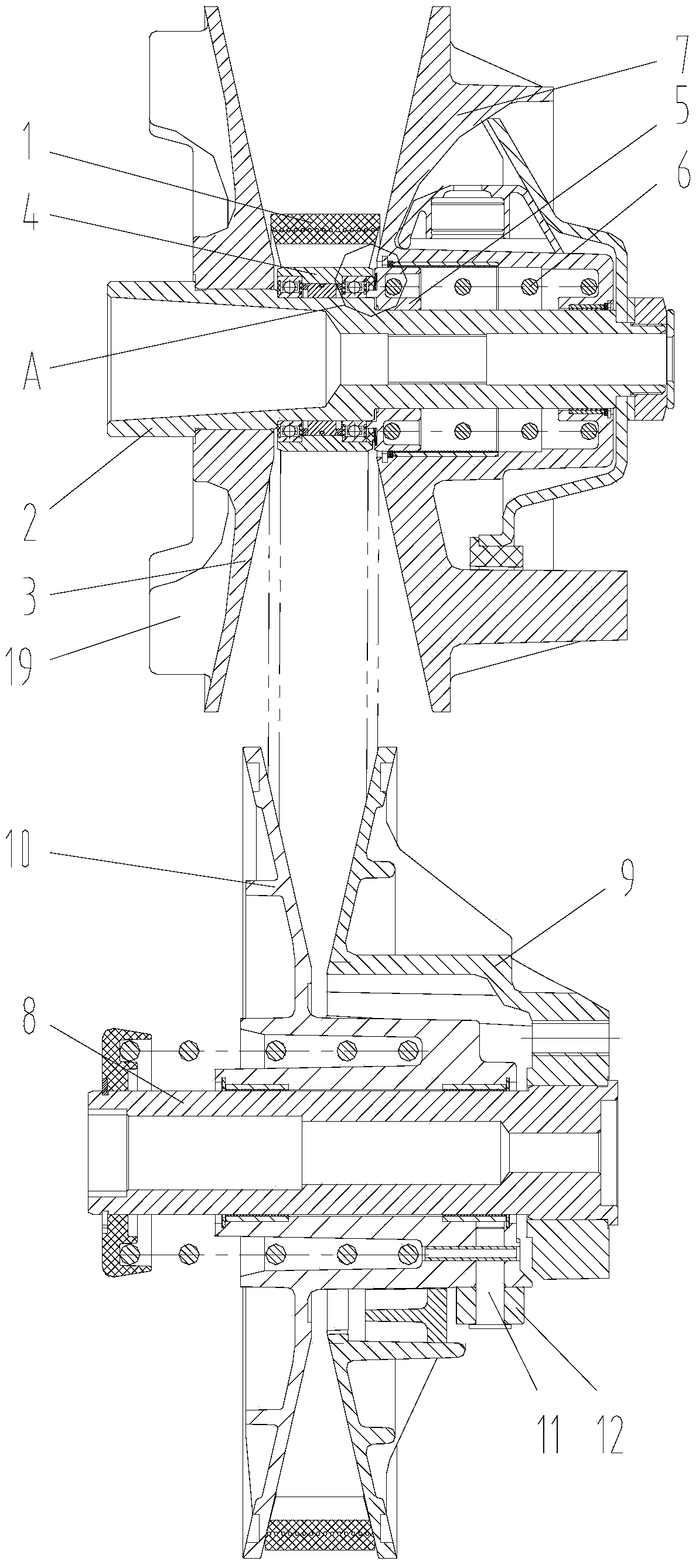
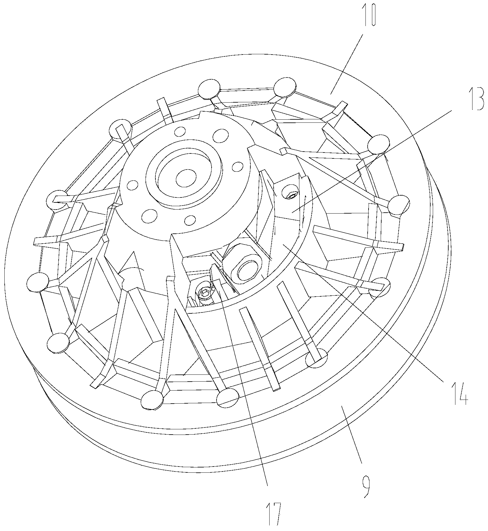
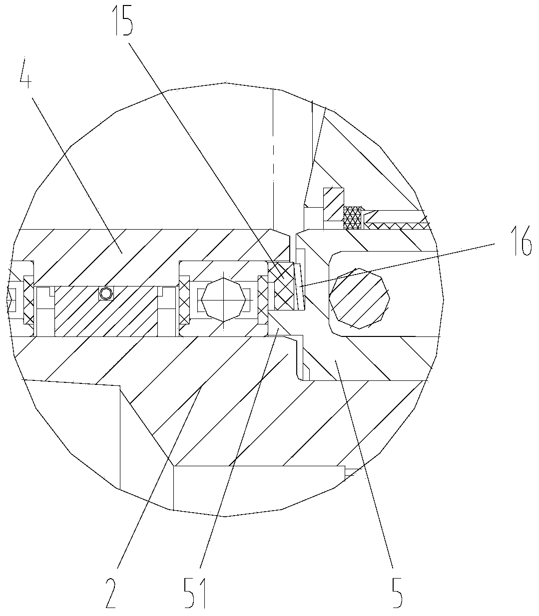
[0023] As shown in the figure, the spiral-guided continuously variable clutch of this embodiment includes a combination of driving wheels, a transmission belt 1 and a combination of driven wheels. 6 and moving wheel 7, the drive plate and the spring seat are fixed on the driving shaft, the bushing is located between the driving plate and the spring seat, and fixed on the driving shaft through rolling bearings, one end of the moving wheel passes through the sliding bearing sleeve On the spring seat, the other end of the moving wheel is sleeved on the driving shaft through a sliding bearing, one section of the spring is pressed against the spring seat, and the other end is pressed against the moving wheel; the driven wheel combination includes a driven shaft 8, A fixed plate 9 fixed on the driven shaft and a moving plate 10 sleeved on the driven shaft thr...


PUM

PropertyMeasurementUnit
Heightaaaaaaaaaa

Abstract

The invention discloses a spiral guiding stepless variable transmission which comprises a driving wheel assembly, a transmission belt and a driven wheel assembly, wherein a radial pin is fixedly arranged at the end part of a moving disc; a roller is arranged on the radial pin; a guiding block is arranged on the fixing disc; a spiral guiding inclined surface is arranged on the guiding block; the driving wheel assembly further comprises a synchronous ring and a disc spring; the synchronous ring leans against the outer ring of a rolling bearing; the disc spring leans against the synchronous ring and a spring base. According to the spiral guiding stepless variable transmission disclosed by the invention, the roller and the spiral guiding inclined surface in match with the roller are adopted to guide the movement track of a moving wheel in the speed change process, the friction between the moving wheel and the transmission belt is small, and the transmission belt has less abrasion and is long in service life; moreover, when an automobile is accelerated to start and speed up from an idle speed state, as the driven wheel assembly has certain rotation speed in the idle speed state, the rotation speed of the driven wheel assembly of the automobile changes stably in the starting and speeding process, and the automobile is good in starting stability.

Description

technical field [0001] The invention relates to a transmission mechanism, in particular to a continuously variable clutch. Background technique [0002] Usually, the continuously variable clutch includes a driving wheel combination, a driven wheel combination and a transmission belt. The driving wheel combination is connected with the engine crankshaft. When the engine crankshaft rotates, the driving wheel drives the driven wheel to rotate through the transmission belt to output power. [0003] The driven wheel combination includes a moving plate and a fixed plate, and the transmission belt is located between the moving plate and the fixed plate. During the speed change process, the transmission belt pushes the moving plate to move axially along the driven shaft to change the diameter of the transmission belt on the moving plate and the fixed plate. to the position to realize the speed change. [0004] In the continuously variable clutch in the prior art, the moving plate o...

Claims


Application Information

Patent Timeline
IPC IPC(8): F16H9/14
CPCF16H9/14
Inventor 伍怀秋
Owner CHONGQING CHANGXING IND
Why Eureka
Try Eureka