Salt-containing waste liquid combustion and heat energy recycling system and process

A technology for recovery of salty waste liquid and heat energy, which is applied in the direction of incinerators, combustion methods, combustion types, etc., can solve the problems of unstable process operation, irregular follow-up, and irregular discharge, etc., to ensure long-term normal operation, Safe effect of avoiding deposition and recovering salt

Active Publication Date: 2015-02-11
宜兴市智博环境设备有限公司
View PDF5 Cites 9 Cited by
  • Summary
  • Abstract
  • Description
  • Claims
  • Application Information

AI Technical Summary

Problems solved by technology

Due to the different components and concentrations of wastewater, and the irregular discharge, the amount of wastewater discharge and water quality vary greatly

Method used


Image

  • Salt-containing waste liquid combustion and heat energy recycling system and process
  • Salt-containing waste liquid combustion and heat energy recycling system and process
  • Salt-containing waste liquid combustion and heat energy recycling system and process

Examples


Embodiment 1

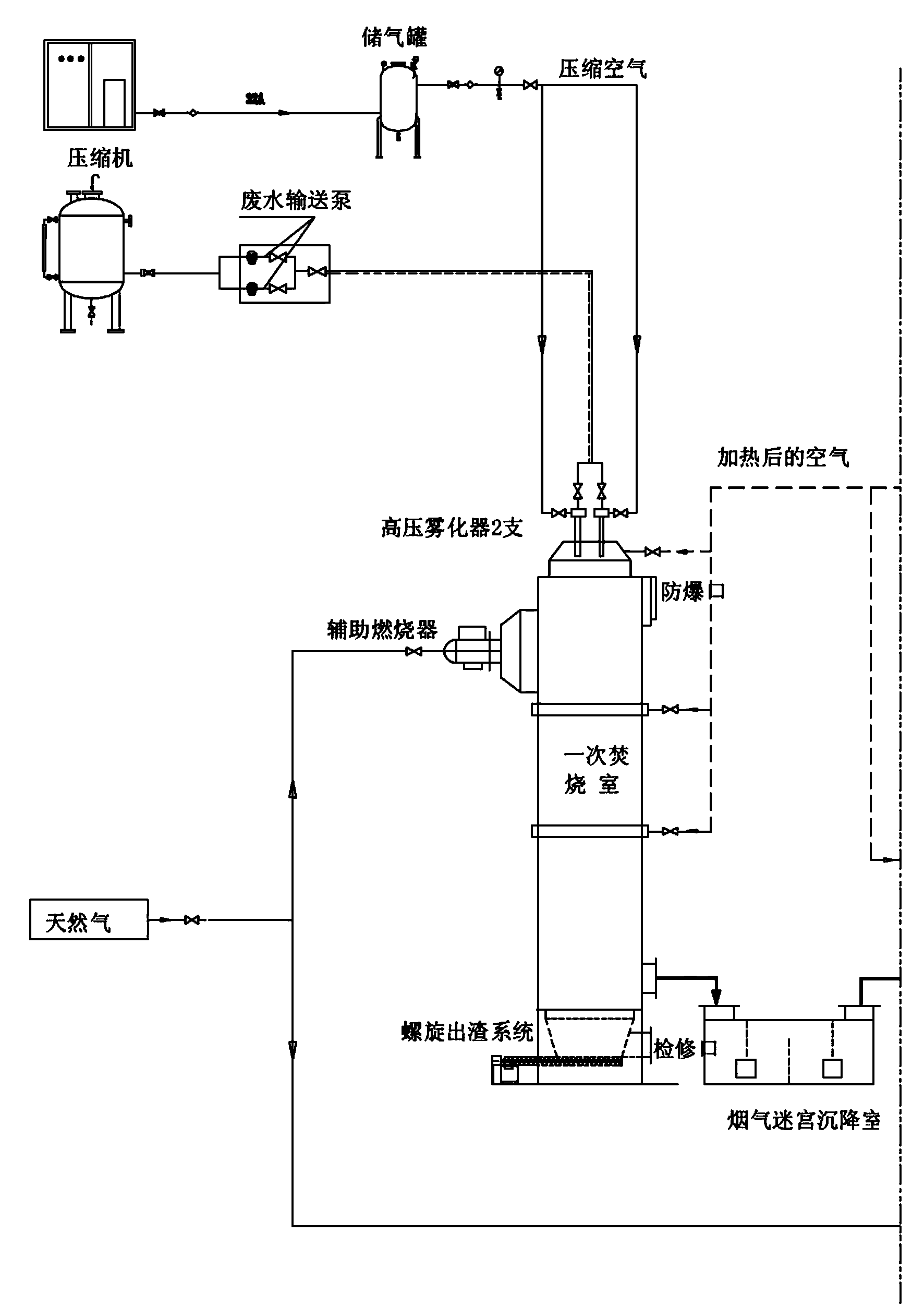
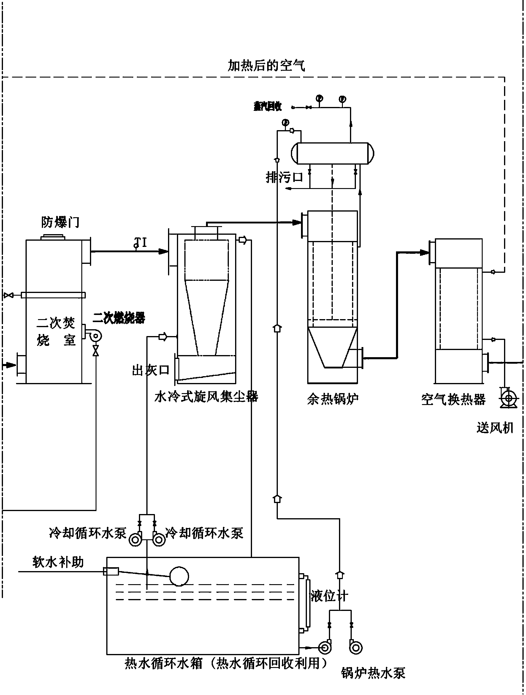
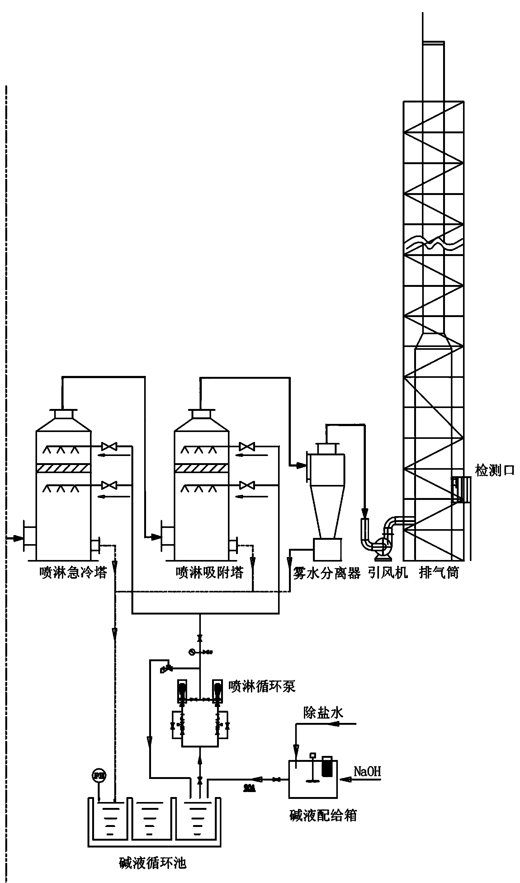
[0037] Such as Figure 1-2 As shown, a saline waste liquid incineration and heat recovery system includes a high-pressure atomization device, a primary incineration chamber, a labyrinth settling chamber, a secondary incineration chamber, a water-cooled cooling dust collector, a waste heat boiler, and an exhaust gas purification device connected in sequence; The labyrinth settling chamber includes a shell, a flue gas inlet and a flue gas outlet, and a plurality of baffles are vertically arranged between the flue gas inlet and the flue gas outlet in the shell, and the baffles are arranged crosswise so that the flue gas passes through a labyrinthine tortuous route; The length, width and height of the labyrinth settling chamber are set according to the amount of flue gas produced by the calorific value of the incinerated waste liquid, so that the flow velocity of the flue gas in the labyrinth settling chamber is 2-3 m / s, and the flue gas flows in the labyrinth The residence time i...

Embodiment 2

[0043] Such as figure 2 As shown, a saline waste liquid incineration and heat recovery process specifically includes the following steps:

[0044] 1) The saline waste liquid is atomized under high pressure and mixed with air and then enters the primary incineration chamber for incineration treatment; the temperature of the primary incineration is 750-800°C, and the residence time of the atomized waste liquid in the primary incineration chamber is 2 seconds;

[0045] 2) The flue gas produced in the primary incineration chamber is introduced into the labyrinth-type settling chamber for sedimentation treatment to remove large particles of salt particles and dust in the flue gas; the flue gas after primary incineration passes through the labyrinth-type settling chamber at 2.5 m / s The second speed passes, and the residence time of the flue gas in the settling chamber is controlled at 2 seconds.

[0046] 3) The residual flue gas after step 2) is introduced into the secondary incin...


PUM

PropertyMeasurementUnit
Melting pointaaaaaaaaaa

Abstract

The invention discloses a salt-containing waste liquid combustion and heat energy recycling system which comprises a high-pressure atomization device, a primary combustion chamber, a labyrinth deposition chamber, a secondary combustion chamber, a water-cooling type cooling dust collector, a waste heat boiler and a tail gas purification device which are connected in sequence, wherein the labyrinth deposition chamber comprises a shell, a fume inlet and a fume outlet; a plurality of baffles are arranged vertically between the fume inlet and the fume outlet of the shell; the baffles are arranged in a cross manner, so that fume can pass through along a labyrinth curved route. Compared with the prior art, the salt-containing waste liquid combustion and heat energy recycling system is relatively safe, sufficient and thorough in recycling salt before the waste heat is recycled, prevents deposition of the salt in the waste heat boiler or a pipeline, effectively improves the waste heat recycling efficiency and ensures long-lasting normal operation of equipment.

Description

technical field [0001] The invention relates to an incineration treatment and heat energy recovery system of chemical waste liquid, in particular to a system and process for incineration treatment of waste liquid with high salinity and lye content and recovery and incineration of waste heat steam. Background technique [0002] There are many types of wastewater produced in the chemical production process. The composition and concentration of each wastewater vary with raw materials and processes. There are raw materials, by-products, degradation products, and raw and auxiliary materials, forming a large amount of toxic and harmful high-concentration waste liquid, etc. The pollutants in wastewater have complex components, high chroma, and most of them have a strong pungent odor. It is one of the most difficult wastewater to treat at present. [0003] The water quality of many chemical waste liquids varies greatly. Due to the different components and concentrations of wastewat...

Claims


Application Information

Patent Timeline
IPC IPC(8): F23G7/04F23J15/02F23L15/00F23J15/06
CPCF23G7/04F23J15/022F23J15/06F23L15/00Y02E20/34
Inventor 王志军
Owner 宜兴市智博环境设备有限公司
Why Eureka
Try Eureka