Outdoor machine of air conditioner

A technology for outdoor units and air conditioners, applied in the field of outdoor units, can solve problems such as top panel deformation, achieve the effects of increasing productivity, preventing deformation, and improving installation workability

Active Publication Date: 2015-02-11
MITSUBISHI ELECTRIC CORP
View PDF10 Cites 5 Cited by
  • Summary
  • Abstract
  • Description
  • Claims
  • Application Information

AI Technical Summary

Problems solved by technology

For example, when the outdoor unit is stacked in a warehouse and a load is applied from above the top panel, there is a problem that the top panel deforms depending on the magnitude of the load because there is no part to support it from the back of the top panel.

Method used


Image

  • Outdoor machine of air conditioner
  • Outdoor machine of air conditioner
  • Outdoor machine of air conditioner

Examples


Embodiment approach 1

[0035] Hereinafter, the outdoor unit of the air conditioner according to Embodiment 1 of the present invention will be described in detail using the drawings.

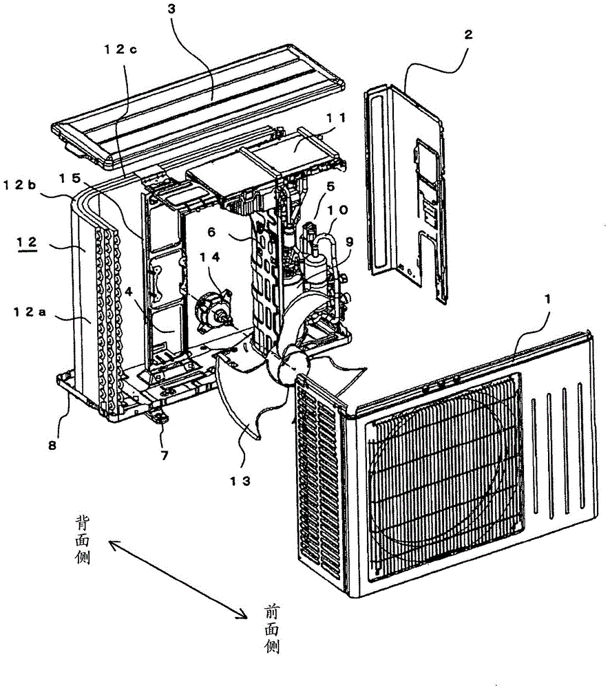
[0036] figure 1 It is an exploded perspective view showing an outdoor unit (hereinafter, sometimes simply referred to as an outdoor unit) of the air conditioner according to Embodiment 1 of the present invention. like figure 1 As shown, a plurality of panels, such as a front panel 1 , a side panel 2 , a top panel 3 , and a bottom panel 8 constitute a roughly rectangular parallelepiped frame of the outdoor unit. The plurality of panels are all made of metal plates. The front panel 1 is substantially L-shaped in horizontal cross-section, and constitutes the front portion of the housing, and also constitutes the side surface portion on the opposite side of the side panel 2 . The top panel 3 constitutes the top surface of the outdoor unit frame. Furthermore, a heat exchanger (described later) is arranged on the back ...

Embodiment approach 2

[0070] In Embodiment 1, when the top panel 17 is slid, the fan motor support plate side fitting portion 16c is formed by cutting and rising in an L-shape in cross section, and the rear side of the fitting portion on the top panel horizontal surface 17m is The end surface 17a and the top panel side fitting part 17b are slid to the lower side of the L-shaped support horizontal surface 16m, and movement in the up-down direction is restricted. In Embodiment 2 of the present invention, another configuration example of the fitting portion will be described. When the top plate 17 is slid, the movement in the vertical direction of the top plate 17 is restricted, and the top plate 17 is positioned relative to the fan motor support plate 16. Align in the up and down direction.

[0071] Figure 8 It is an explanatory diagram showing the fitting portion of the fan motor support plate 16 and the top plate 17 according to Embodiment 2 of the present invention. Figure 8 (a) is a plan view...

Embodiment approach 3

[0080] In Embodiment 1, Figure 7 The shown guide portion 16f has a function of restricting the movement of the top panel 17 in the left-right direction W and positioning the top panel 17 when the operator slides the top panel 17 from the front side to the rear side with respect to the fan motor support plate 16, but is not limited to Figure 7 The structure of the guide portion 16f is shown. The function of the guide portion is to position the fan motor support plate 16 and the top plate 17 to face each other in the left-right direction W when the top plate 17 is slid. By positioning the fan motor support plate 16 and the top plate 17 in the left-right direction relative to each other by using the guide, the fan motor support plate side fitting portion 16c of the fan motor support plate 16 and the top plate side fitting portion 17b of the top plate 17, and The threaded holes 16e for fixing the top plate and the threaded holes 17e of the fan motor support plate are aligned in...


PUM


Abstract

An outdoor machine of an air conditioner includes a fan motor mount including a fan motor support plate, and a top plate. The fan motor support plate is formed with: a plurality of props; a prop horizontal plane; a prop front plane; a fitting portion, which is provided on the prop horizontal plane and fitted to a rear end of the top plate; and a first screw hole, which is provided on the prop front plane to fix the top plate. The top plate is formed with: a screw fixing piece, which has a shape parallel to the prop front plane and is provided with a second screw hole corresponding the first screw hole. The fitting portion is fitted to the rear end of the top plate, and the screw fixing piece is located on the front side of the prop front plane.

Description

technical field [0001] The present invention relates to an outdoor unit of an air conditioner, and in particular to a structure of a fan motor mounting table for supporting a fan motor. Background technique [0002] In the outdoor unit of an air conditioner, the inside of the frame is partitioned left and right by a partition plate erected on the base plate constituting the bottom of the frame into the blower room where the blower fan and heat exchanger are located, and the compressor and refrigerant piping. The mechanical room where it is located. In addition, electrical and electronic components for controlling the operation of the air conditioner are arranged mainly in the upper portion of the machine room. [0003] In the blower room, the heat exchanger with a substantially L-shaped horizontal section is arranged from the back side of the frame to the side side opposite to the machine room, and the front side of the frame is placed in front of the heat exchanger on the ...

Claims


Application Information

Patent Timeline
Patent Type & Authority Applications(China)
IPC IPC(8): F24F1/22F24F13/32
CPCF24F1/38F24F1/16F24F1/46
Inventor 阵内宽之久保野俊行大石一广
Owner MITSUBISHI ELECTRIC CORP
Why Eureka
Try Eureka