Incubator lighting circuit

A lighting circuit and thermostat technology, applied in lighting devices, electric lamp circuit layout, electric light source, etc., can solve the problems of low test efficiency, affect the test environment, inconvenient operation, etc., achieve safe and reliable work efficiency, ensure rigor and accuracy degree, improve work efficiency

Inactive Publication Date: 2015-02-11
OCEANKING DONGGUAN LIGHTING TECH +2
View PDF0 Cites 2 Cited by
  • Summary
  • Abstract
  • Description
  • Claims
  • Application Information

AI Technical Summary

Problems solved by technology

[0003] When the product is placed in the incubator, there is only a small transparent window on the incubator for the tester to observe, while the inside of the incubator is completely dark. During the test, the tester generally needs to open the door of the incubator to observe the product. Once the door of the incubator is opened, it will easily affect the test environment and cause inaccurate test data; another observation method is to use a flashlight for irradiation. If there is not necessarily a flashlight on site, it is necessary to look for a flashlight, which is very inconvenient to operate and leads to Inefficient testing

Method used


Image

  • Incubator lighting circuit
  • Incubator lighting circuit

Examples


Embodiment 1

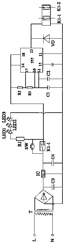
[0027] Please refer to figure 1 or figure 2 , The incubator lighting circuit of the present invention includes a power supply module, a light emitting element, a button switch and a delay control circuit, a first resistor R1, a third capacitor C3 and a fourth capacitor C4.

[0028] The power module is used to supply power to the light-emitting element and the delay control circuit. The power module includes a power live wire L, a power neutral wire N and a rectifier module. The rectifier module is used to reduce the AC voltage at the input end of the power module and convert it into a DC voltage. The rectifier module includes a transformer T, a bridge stack BD and a voltage regulator IC. The transformer T is used to convert the 220V AC voltage into a 12V AC voltage, and the bridge stack BD is used to convert the 12V AC voltage into a 12V DC voltage. The tube IC is a three-terminal regulator tube 7812, which can output a stable DC voltage, which includes an input terminal, a ...

Embodiment 2

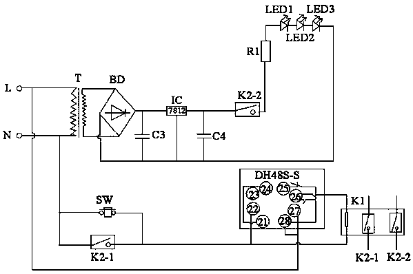
[0038] Please refer to figure 2 , is a circuit diagram of another embodiment of the incubator lighting circuit of the present invention. The difference from the first embodiment is that the delay module includes a time relay DH48S-S and a relay K2, and the time relay DH48S-S includes 8 pins. Respectively, the first pin 21, the second pin 22, the third pin 23 for time reset, the fourth pin 24, the fifth pin 25, the sixth pin 26, the The seventh pin 27 and the eighth pin 28, the power module is connected between the second pin 22 and the seventh pin 27, the second pin 26 is connected to the neutral line N of the power supply, the seventh pin 27 and the eighth pin 28 is connected to the live wire L of the power supply, the fifth pin 25 is the normally closed contact of the internal relay, and the sixth pin 26 is the normally open contact of the internal relay.

[0039] The relay K2 includes a first normally open contact K2-1 and a second normally open contact K2-2, and the butt...


PUM


Abstract

The embodiment of the invention discloses an incubator lighting circuit comprising a power supply module, a light-emitting element, a button switch and a time-delay control circuit. The power supply module is used for supplying power to the light-emitting element and the time-delay control circuit. The light-emitting element is arranged in the internal part of an incubator. The time-delay control circuit comprises a relay and a time-delay module. The relay comprises a first normally-open contact which is connected in parallel with the button switch. The light-emitting element is connected in parallel with the time-delay module and then connected in series with the relay. With application of the incubator lighting circuit, the product state in the incubator can be observed by test personnel without opening the incubator so that strictness and accuracy of incubator test data are guaranteed. The light-emitting element can be controlled to be off automatically by the time-delay control circuit so that work efficiency of the test personnel is enhanced.

Description

technical field [0001] The invention relates to the field of thermostat monitoring, in particular to a thermostat lighting circuit. Background technique [0002] Environmental test is one of the important factors to measure the performance of a product, and also one of the important indicators to evaluate the reliability of a product. In the stage of new product development engineering prototype, small batch test or product type test test, tests such as high temperature, low temperature, constant damp heat and alternating damp heat are required. When these products are tested, the products need to be placed in the incubator. According to the industry standards, national standards or international standards of different industries, the temperature of the incubator is set according to the standard conditions, and the conditions of the environmental test are adjusted. [0003] When the product is placed in the incubator, there is only a small transparent window on the incubato...

Claims


Application Information

Patent Timeline
Patent Type & Authority Applications(China)
IPC IPC(8): H05B37/02
CPCY02B20/40
Inventor 周明杰胡波
Owner OCEANKING DONGGUAN LIGHTING TECH
Why Eureka
Try Eureka