Drilling reaming bit machine tool

A technology of machine tools and reaming, which is applied in the direction of metal processing machinery parts, clamping, support, etc., can solve the problems affecting the process layout of the machining center, the high cost of the machining center, and the failure to meet the requirements, etc., to achieve high precision in batches and small quantities Contradictions in high-precision production planning, solving complex problems, and the effect of solving processing costs

Inactive Publication Date: 2015-02-18
南京金宇刀具制造有限公司
View PDF0 Cites 0 Cited by
  • Summary
  • Abstract
  • Description
  • Claims
  • Application Information

AI Technical Summary

Problems solved by technology

[0002] Certain processes of processing some parts cannot be realized by general-purpose machine tools, or cannot meet the requirements well. For example, some special-shaped parts cannot be processed by general-purpose machines, and some can barely be processed, but certain precision requirements are too high to meet the requirements. Require
Although some can be processed and the accuracy can be guaranteed, but the auxiliary time is too long, or the economic effect is not good, or the operator's workload is heavy, etc., it is necessary to design a special machine tool
[0003] Dragon rib parts are the main structural supports of textile machines, and there are some special holes that need to be precisely positioned. Using traditional boring and milling and other processing methods can ensure the accuracy of the holes and the position accuracy of the two holes, but the cost of the machining center is relatively high. , there is no special fixture, each clamping time is too long, the batch of parts is large, which affects other process layouts of the machining center, long working hours, and high labor costs

Method used


Image

  • Drilling reaming bit machine tool
  • Drilling reaming bit machine tool

Examples


Embodiment Construction

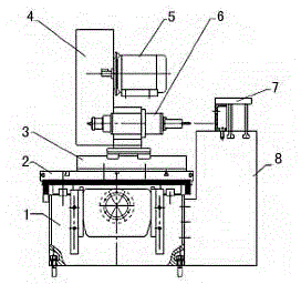
[0013] A drilling and reaming machine tool proposed by the present invention will be described in detail below in conjunction with the accompanying drawings.

[0014] Such as figure 1 As shown, the drilling and reaming machine tool disclosed by the present invention includes a bed 1, an X-direction feed transmission unit, a horizontal slide table 2, a Y-direction feed transmission unit, a machining center slide table 3, a main transmission module 4, a motor 5, a processing Central main shaft 6, special fixture 7 for dragon tendon and side column 8. The X and Y feed transmission units are all installed in the bed 1, the horizontal slide table 2 is installed on the X feed transmission unit, the machining center slide table 3 is installed on the Y feed transmission unit, and the machining center spindle 6 is connected to the motor 5 through the main transmission module 4, the special fixture 7 for dragon tendon is installed on the side column 8, and the special fixture 7 for dra...


PUM


Abstract

The invention discloses a drilling reaming bit machine tool which comprises a tool body, an X-direction feeding transmission unit, a horizontal sliding table, a Y-direction feeding transmission unit, a processing center sliding table, a main transmission module, a motor, a processing center main shaft and a keel specialized clamp, wherein the X-direction feeding transmission unit and the Y-direction feeding transmission unit are arranged inside the tool body, the horizontal sliding table is arranged on the X-direction feeding transmission unit, the processing center sliding table is arranged on the Y-direction feeding transmission unit, the processing center main shaft is connected onto the motor through the main transmission module, and the keel specialized clamp is arranged on the corresponding position of the processing center main shaft. The drilling reaming bit machine tool is provided with the processing center unit and the keel specialized clamp, a large processing piece and the key size are manufactured in a processing center, so that the precision of all components of the machine tool is fully guaranteed, the problem between the processing precision and the processing cost and between the high quantity high precision production plans and low quantity high precision production plans is solved, the simple structure solves the complicated problem, and the high precision, high efficiency and low cost of processing can be achieved.

Description

technical field [0001] The invention belongs to the technical field of mechanical processing equipment, in particular to a drilling and reaming machine tool. Background technique [0002] Certain processes of processing some parts cannot be realized by general-purpose machine tools, or cannot meet the requirements well. For example, some special-shaped parts cannot be processed by general-purpose machines, and some can barely be processed, but certain precision requirements are too high to meet the requirements. Require. Although some can be processed and the accuracy can be guaranteed, but the auxiliary time is too long, or the economic effect is not good, or the operator's workload is heavy, etc., it is necessary to design a special machine tool. [0003] Long rib parts are the main structural supports of textile machines, and there are some special holes that need to be precisely positioned. Using traditional boring and milling and other processing methods can ensure the...

Claims


Application Information

Patent Timeline
Patent Type & Authority Applications(China)
IPC IPC(8): B23P23/02B23Q3/06B23Q5/40B23Q5/36
CPCB23P23/02B23Q3/06B23Q5/36B23Q5/40
Inventor 陈家林
Owner 南京金宇刀具制造有限公司
Why Eureka
Try Eureka